C2 Series Unboxing Tutorial
C2 Unboxing, Installation and Use Guide
Applicable Model C2 Laser Engraver (14W / 7W)
Version Note: The 14W and 7W versions of C2 differ only in the laser module and the air pump power cable on the mainboard. The installation procedure is exactly the same.
Video version:
1. Unboxing and Package Contents
Check the Accessories
Open the package, take out all accessories, and check them against the list. The main accessories include: X-axis beam, left and right side beams, front beam, rear beam, 7W or 14W laser module, power adapter, data cable, protective backing plate, basswood board, safety goggles, screw pack, and tool kit.
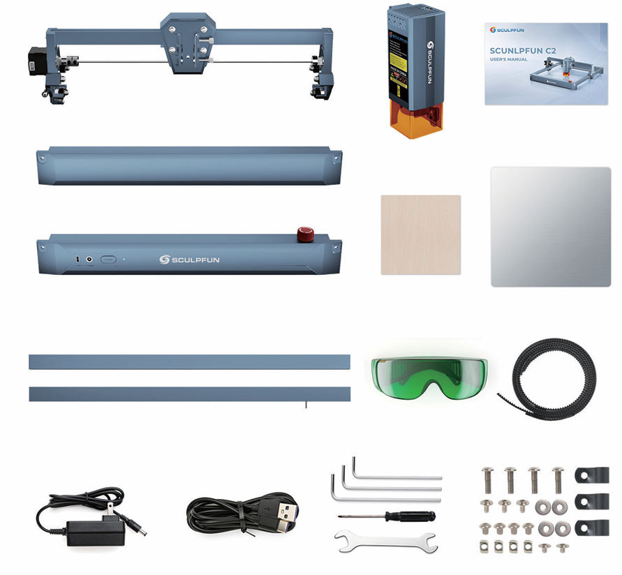
C2 package contents
Get Familiar with the Ports and Indicator Lights
Before installation, get familiar with the locations of the ports and indicator lights so that the later wiring and power-on checks are easier.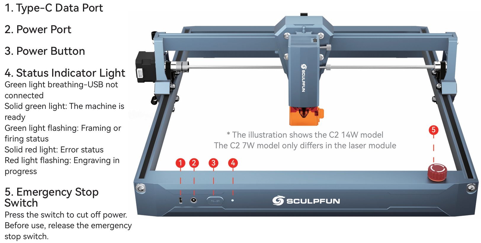
2. Frame Assembly
1. Install the Beam Belt
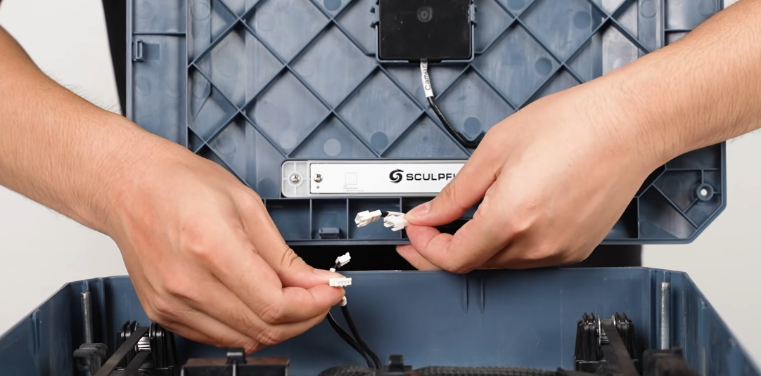
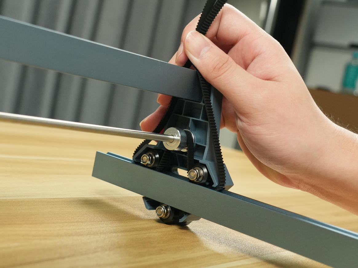
Take out the beam, pass the belt through the bearing, and then pull it upward to tighten it so the side beams can be inserted easily.
2. Insert the Right Side Beam
Insert the right side beam through the belt.
3. Insert the Left Side Beam
Insert the left side beam in the same way.
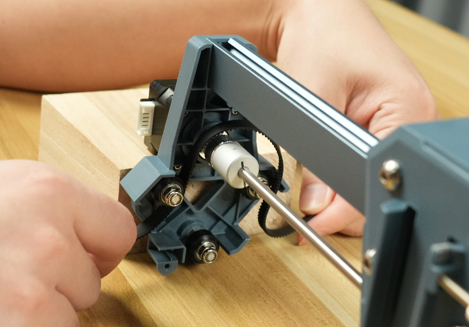
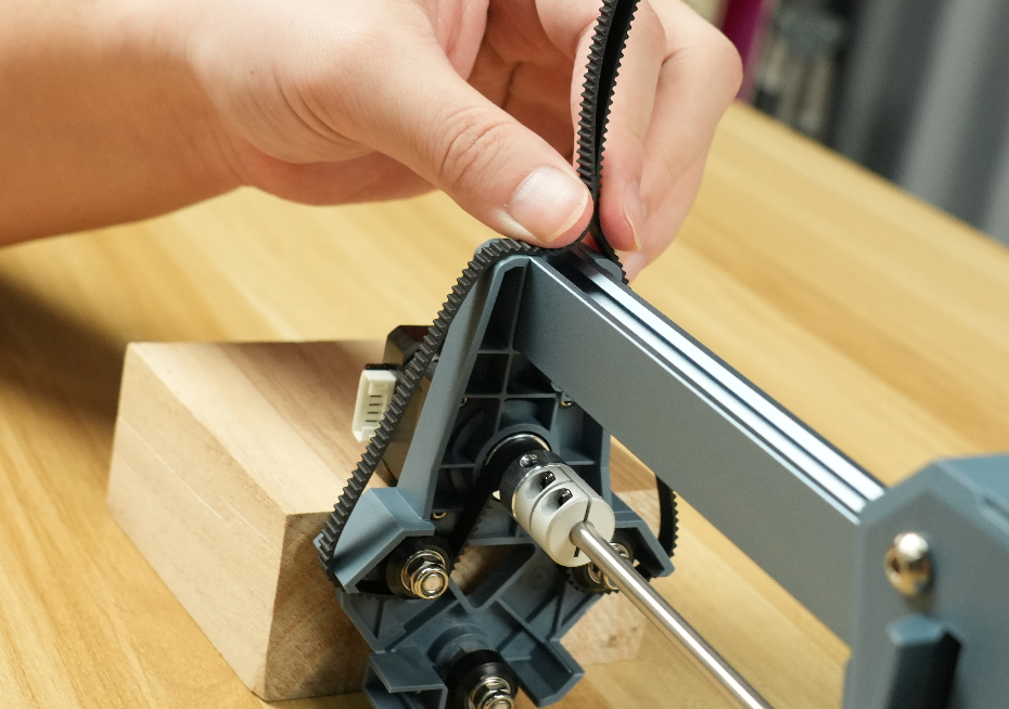
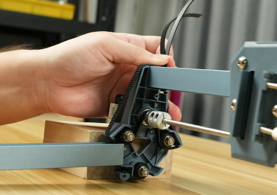
Caution: The left side is the same as the right side, but the limit post must face forward.
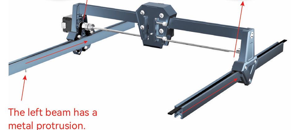
4. Install the Rear Beam
Place the rear beam, pass the rear belt through, rest the left and right side beams on the grooves, and secure them with screws.
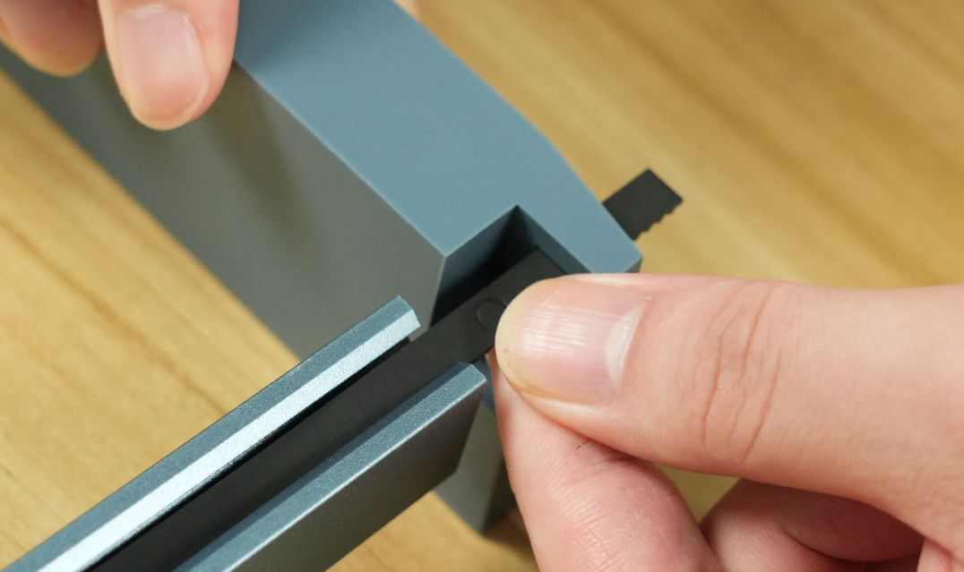
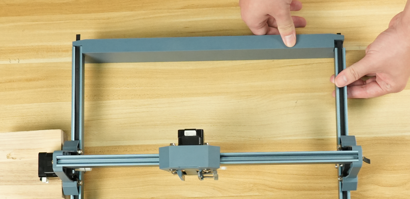
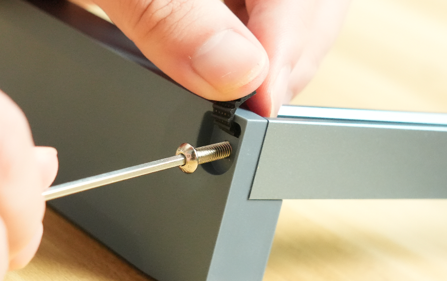
5. Secure the Rear Belt
Use the limit screws to secure the rear belts on both sides to the beam. Make sure the nuts at the bottom are seated in the slots of the beam.
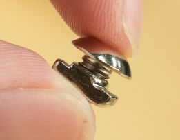
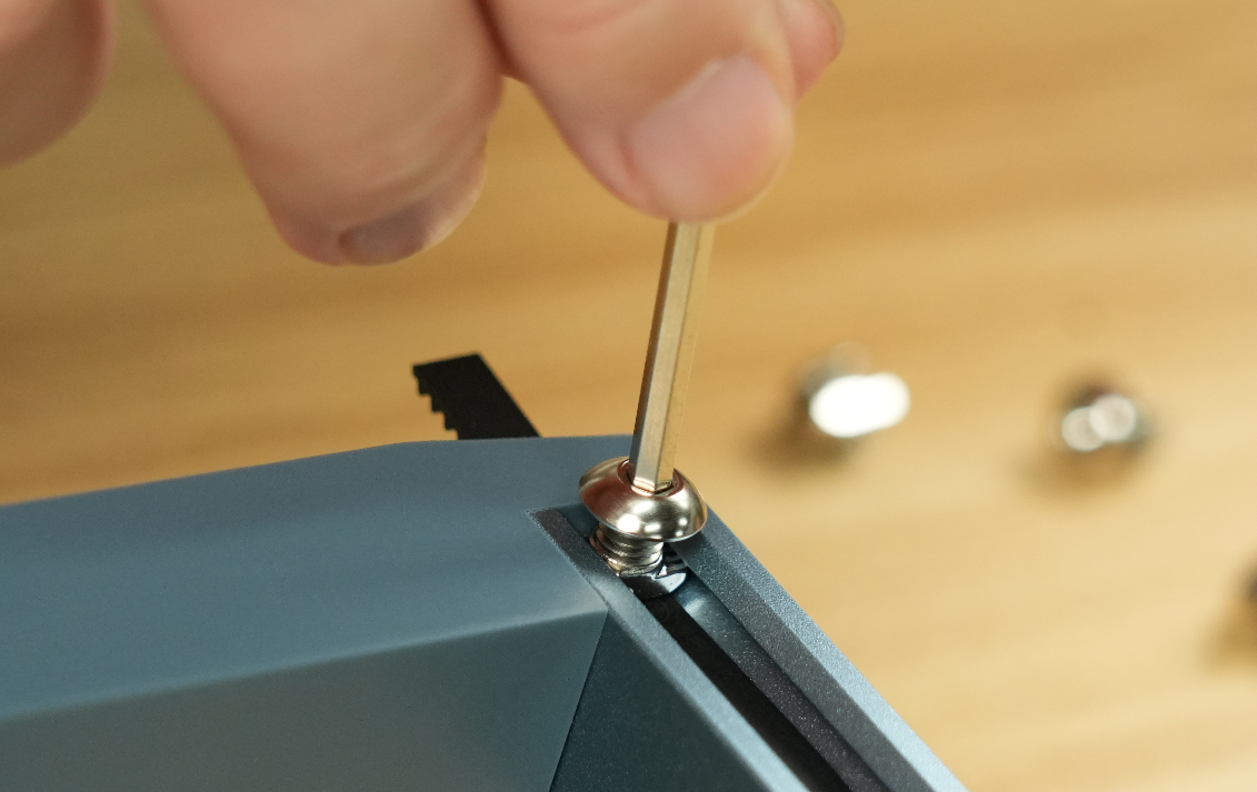
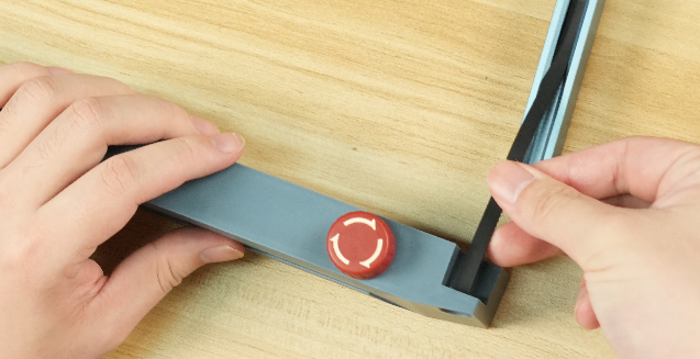
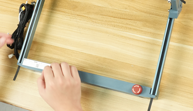
6. Install the Front Beam
First push the X-axis all the way back, then place the front beam, pass the belt through, and tighten the screws.
(Figure)
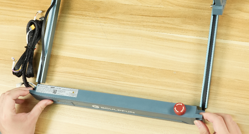
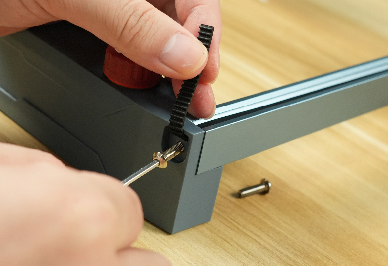
7. Secure the Front Belt
Insert the limit screws to secure the belt. When securing the front belt, you need to tighten the belt first, then tighten the limit screws to lock it.
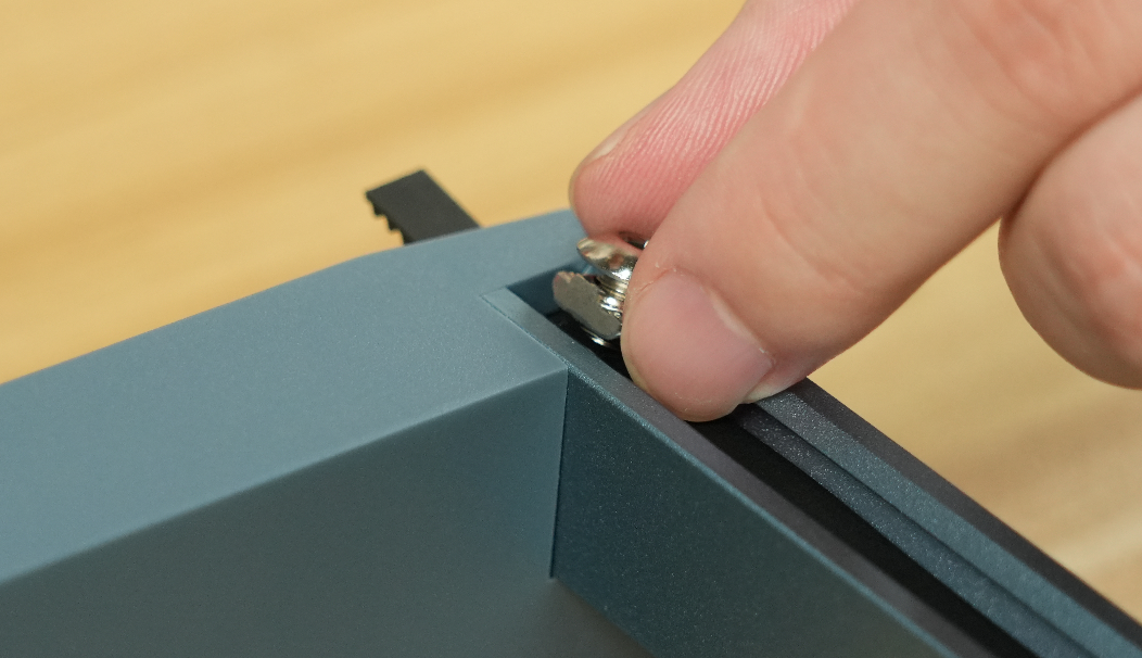
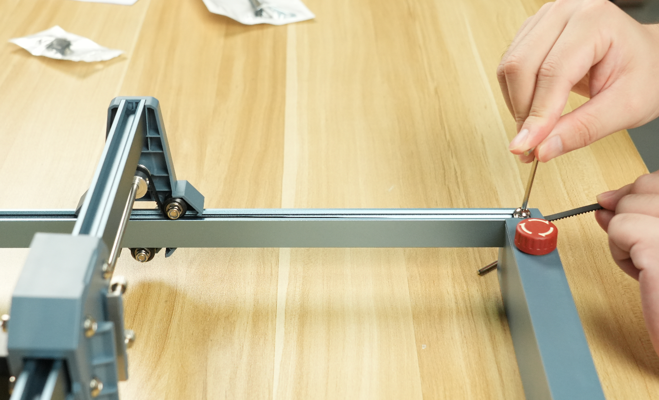
Tip: On both the left and right sides, tighten the belt before tightening the screws; otherwise a loose belt will affect engraving accuracy.
3. Installing the Limit Switches and Cable Clips
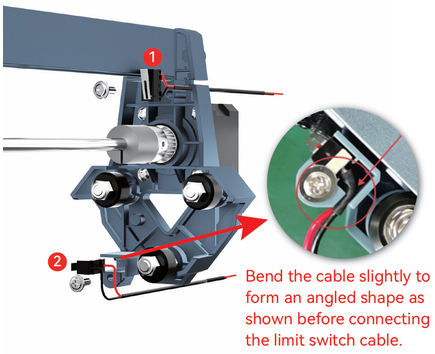
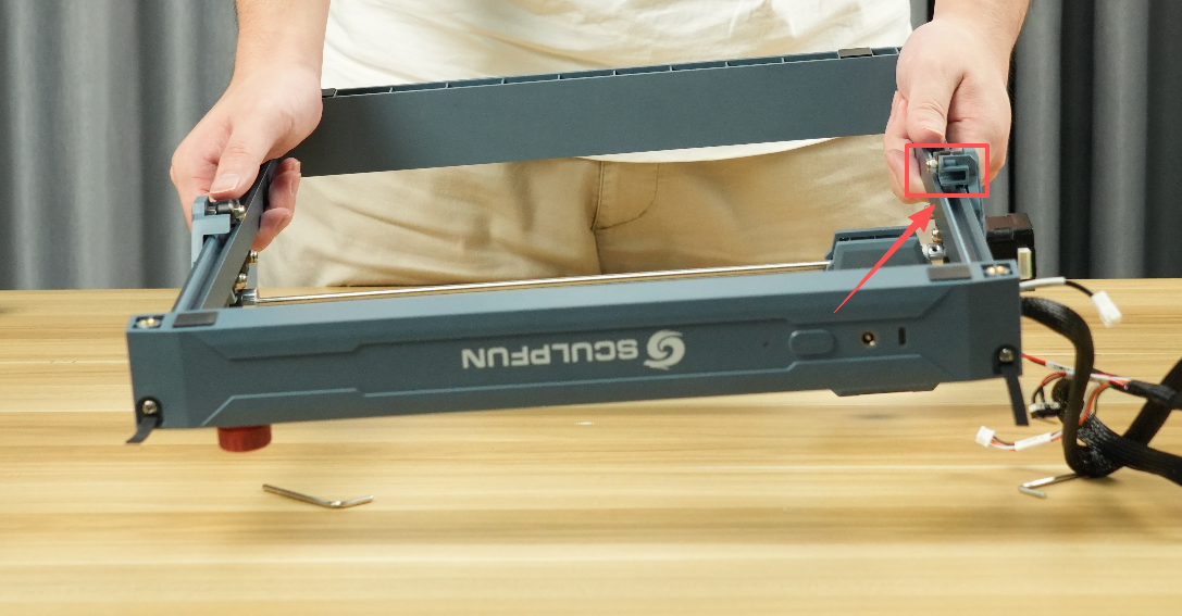
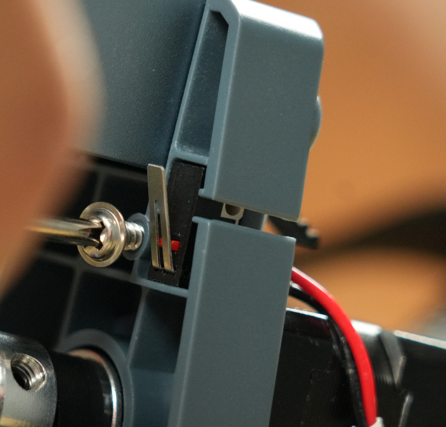
8. Turn the Machine Over and Install the Y-axis Limit Switch
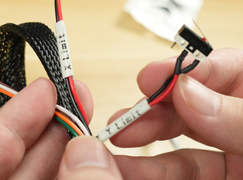
To make installation easier, you can turn the machine over. Open the cable, clip the cable of the Y-axis limit switch into the slot, push the limit switch in, and tighten the screw to lock it.
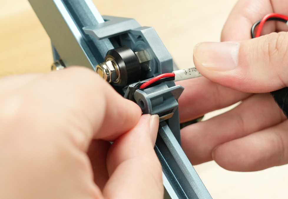
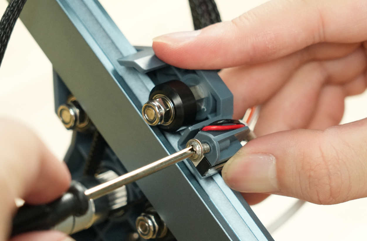
9. Install the X-axis Limit Switch
Turn the machine back upright and install the X-axis limit switch in the same way: clip the cable into the slot, push the limit switch in, and lock it with the screw.
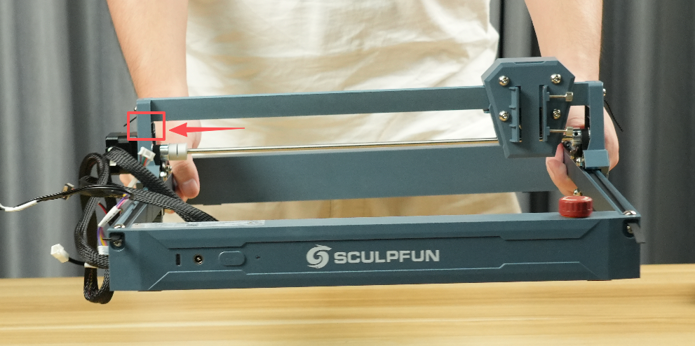
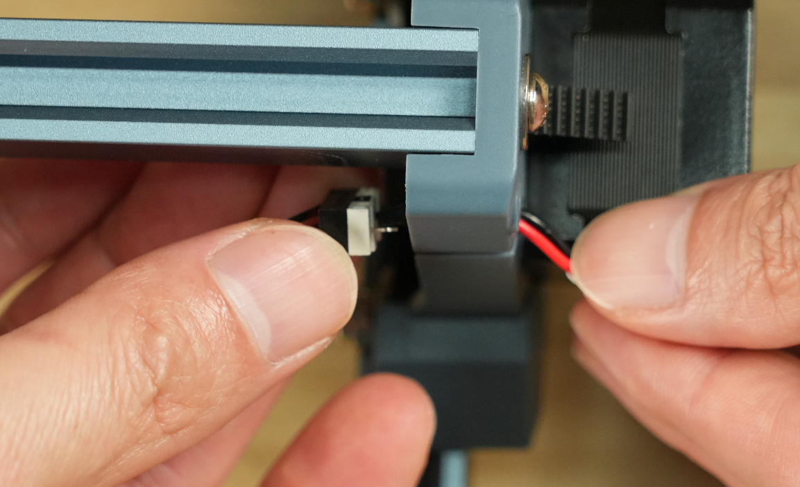
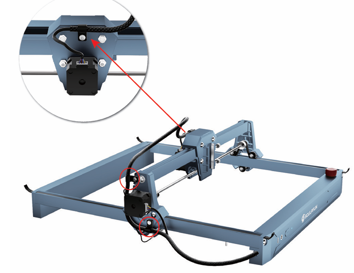
10. Install the Cable Clips
Install the bottom-left cable clip, the upper-left cable clip, and the beam cable clip in turn, clip the cables in, and secure them with screws.
4. Installing the Laser Module and Wiring
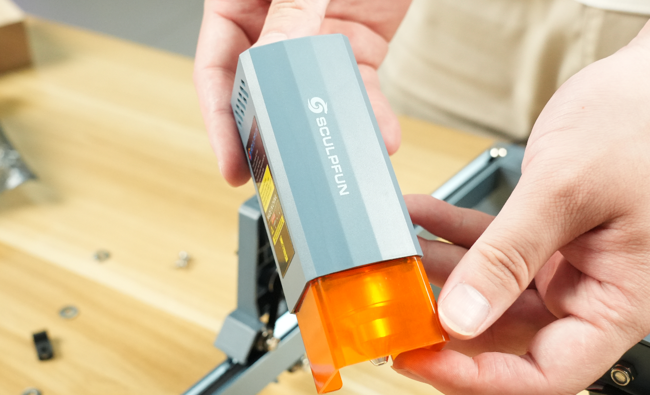
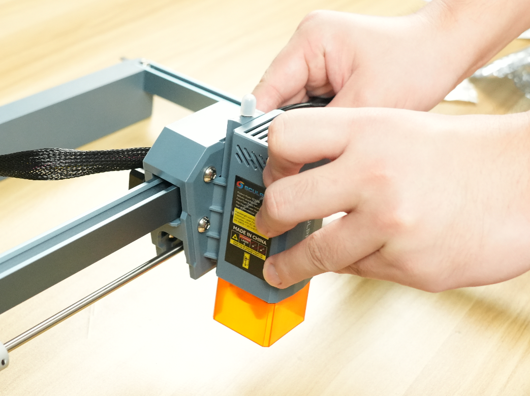
11. Install the Laser Module
Mount the laser module on the beam and plug in the laser module power cable.
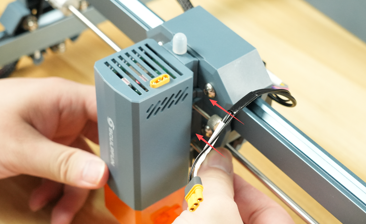
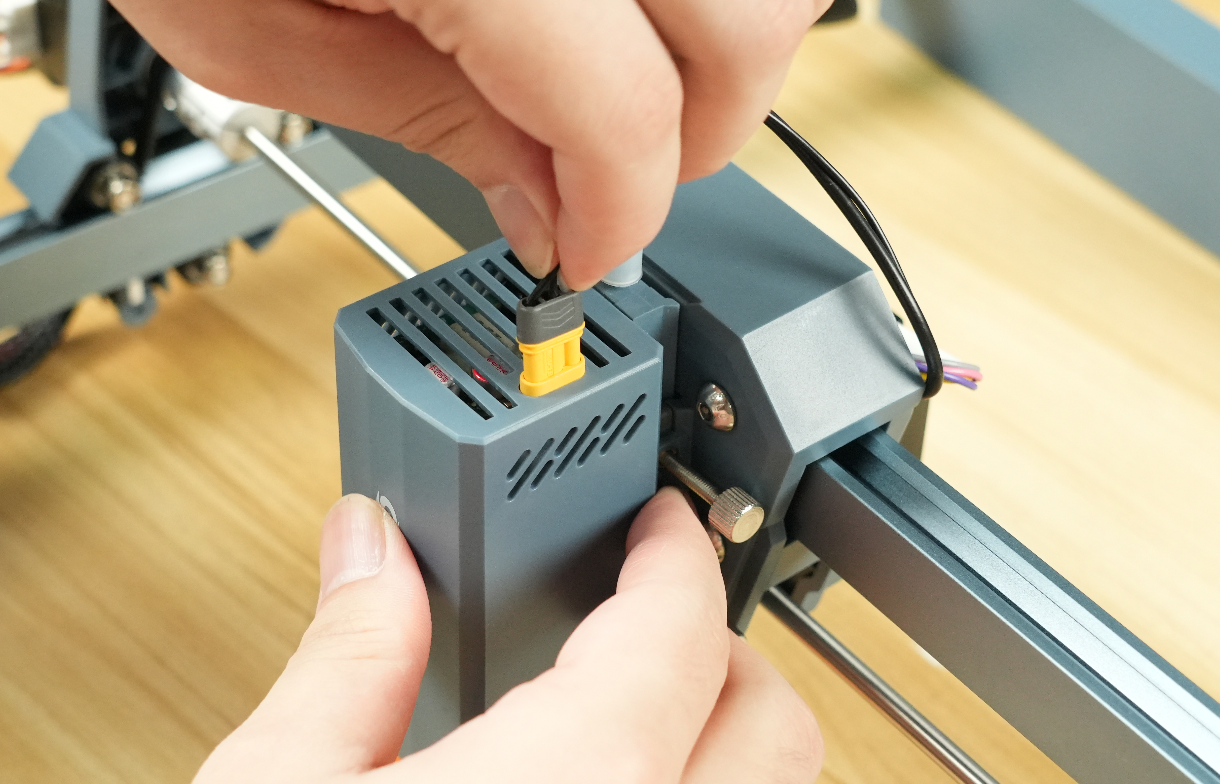
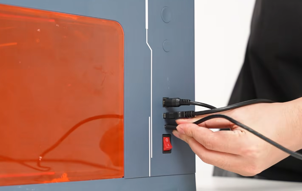
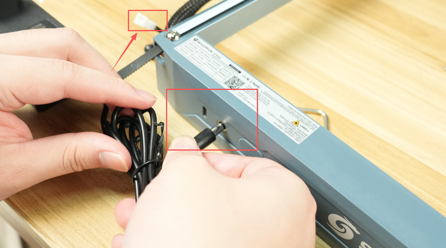
12. Plug In the Power Cable and Data Cable
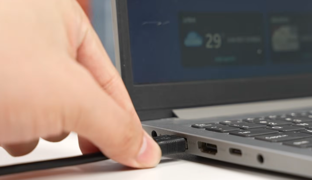
Plug in the power cable and the data cable, and connect the other end of the data cable to your computer.
Tip: The terminal cable is the power cable for the air pump and is included only with the C2 14W machine.
5. Power-on Test
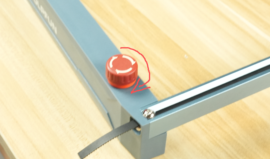
15. Release the Emergency Stop and Power On
Release the emergency stop, then turn on the power, and the machine is ready for use.
Notes
- The limit post must face forward when the side beams are inserted.
- When securing the front and rear belts, always tighten the belt before tightening the screws to avoid a loose belt affecting accuracy.
- Always carry out wiring and disassembly with the power disconnected.