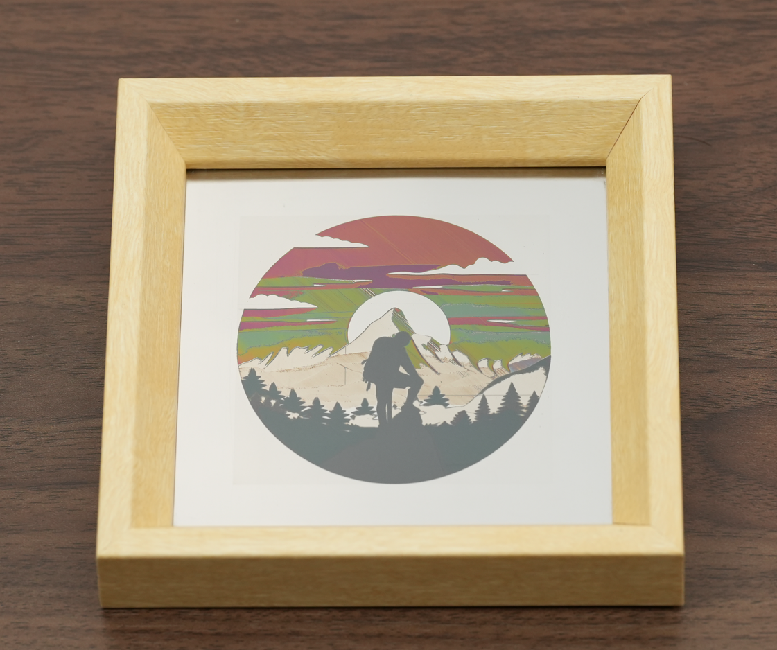
G20 Advanced Tutorial – Color Carving Tutorial
G20 / V12 Color Marking Operation Tutorial
Applicable Models G20, G60, V12 Laser Engravers
This tutorial uses G20 marking on mirror 304 stainless steel as demonstration material.
Before Operation: Principles & Preparation
Color Marking Principle
Non-MOPA lasers process the oxide layer on metal surfaces such as titanium alloy and stainless steel to form oxide films of varying thicknesses. The oxide films produce visible light interference, generating colors including blue, gold, purple and more to realize color marking effects.
Factors Affecting Color Marking Results
- Physical Conditions: Marking results are affected by workpiece material, processing environment, and minor differences between batches of the same material.
- Parameter Conditions: Color results are closely related to Speed, Power, Frequency, Pulse Width, Focal Length and Line Spacing.
Important Reminder: Color marking results are extremely sensitive to changes in processing conditions with a steep learning curve. Multiple rounds of testing are required to achieve stable results.
Testing Recommendations
Test materials and parameters before formal engraving to confirm target color effects. Always use workpieces from the same batch for testing and formal marking to guarantee consistent colors.
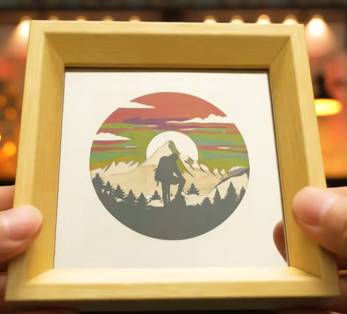
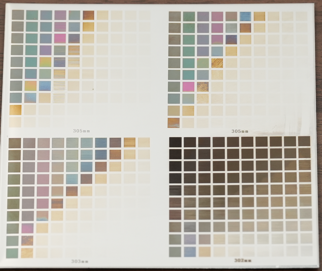
Figure: Mirror 304 stainless steel test workpiece
1. Parameter Testing
Objective: Use material matrix testing to find parameter combinations for target colors and save as a test file for direct reuse in subsequent color marking.
1. Preparation
Connect the machine and launch software, draw a 4×4mm filled rectangle at the canvas center.
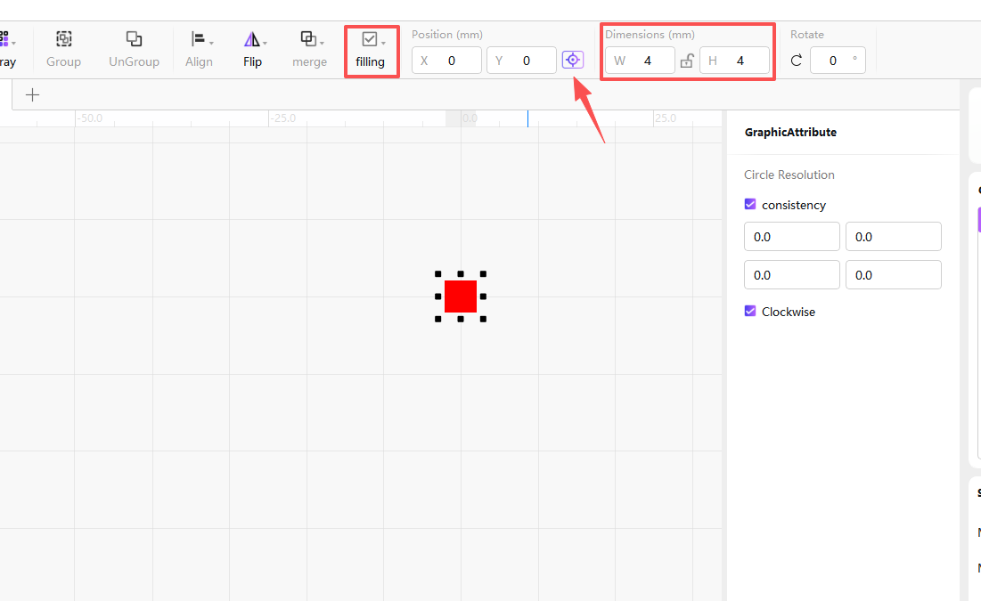
Draw and fill a 4×4mm rectangle
This test fixes frequency and line spacing while varying speed, power and focal length. You may set other variables independently to test different marking effects.
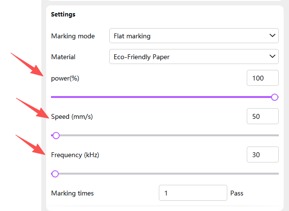
Select the rectangle and set a fixed frequency (30kHz used as example here).
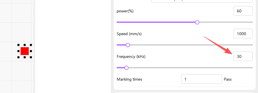
2. Open Material Matrix Test
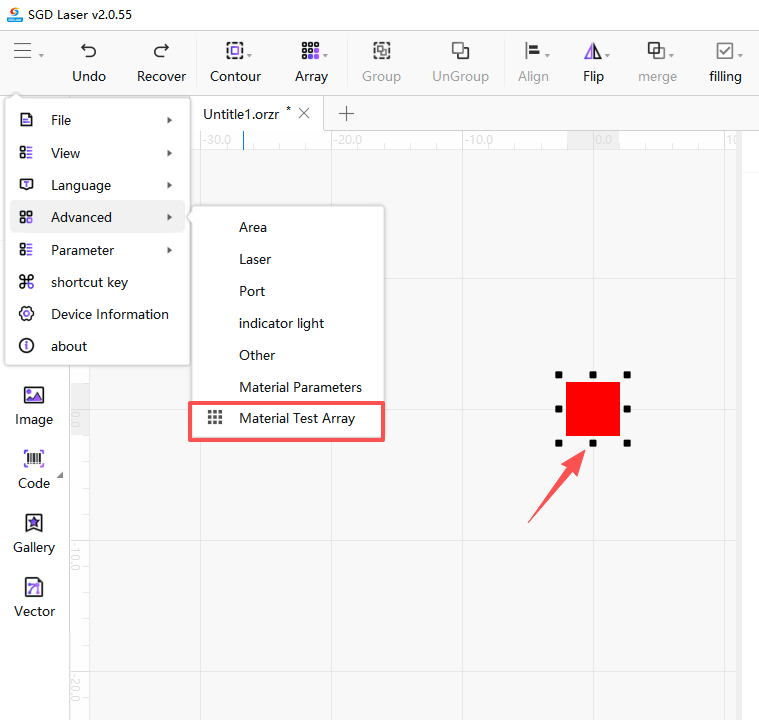
Select the graphic, click top menu Advanced Settings → Material Matrix Test.
3. Configure Test Parameters
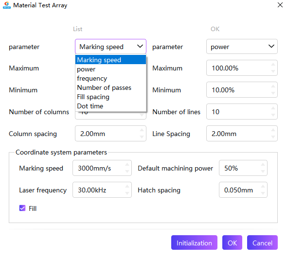
Speed range is normally set to 50–600 mm/s, power range 0–100%. A 10×10 array is used for this test with settings shown below:
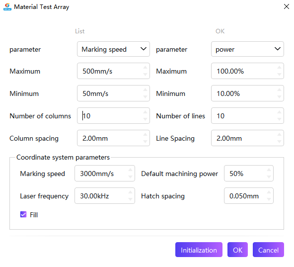
Test parameter settings
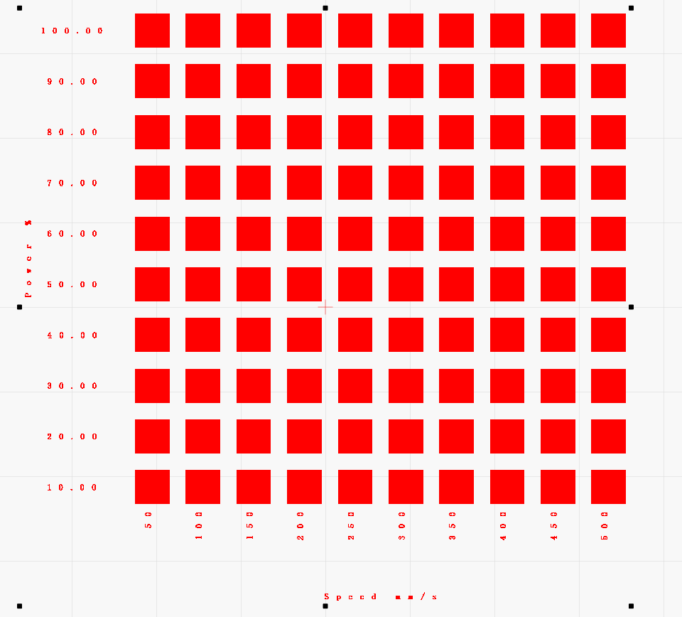
Click Confirm, and the software will auto-generate the material test array.
4. Place Workpiece & Focus
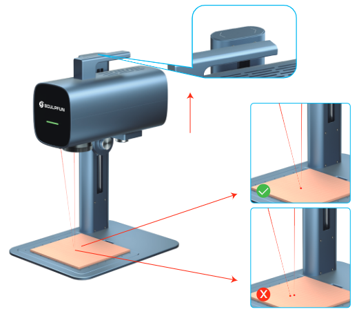
Position the workpiece, then enable focusing light at the software bottom right for focusing. Focusing completes when the two light spots overlap perfectly.
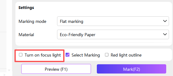
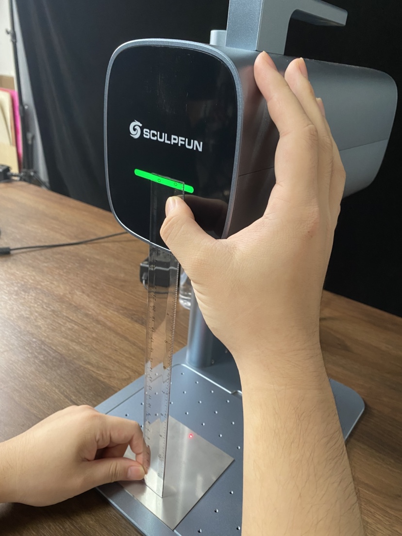
After focusing, measure the focal length with a ruler for subsequent defocus adjustment. For easier measurement and recording, you may directly measure the distance between workpiece surface and laser indicator light.
About Defocus: Identical parameters will produce different colors with altered focal length (defocus). Therefore focal length is one of the core variables for color marking.
5. Set Defocus Offset
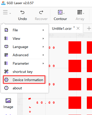
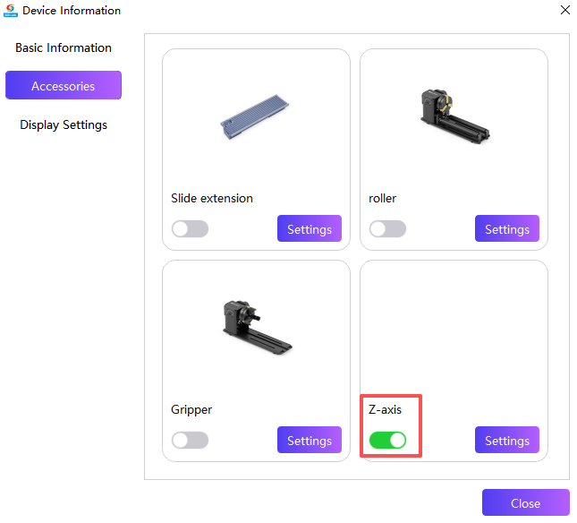
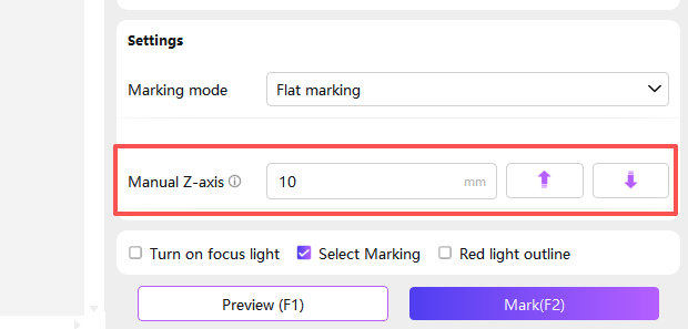
Open menu Device Information and confirm the Z-axis switch is enabled.
Return to canvas and set Z-axis lifting distance at bottom right. Defocus range is normally ±5mm of standard focal length; test in 0.5–1mm increments. This example uses a 4mm positive defocus offset.
6. Preview & Start Processing
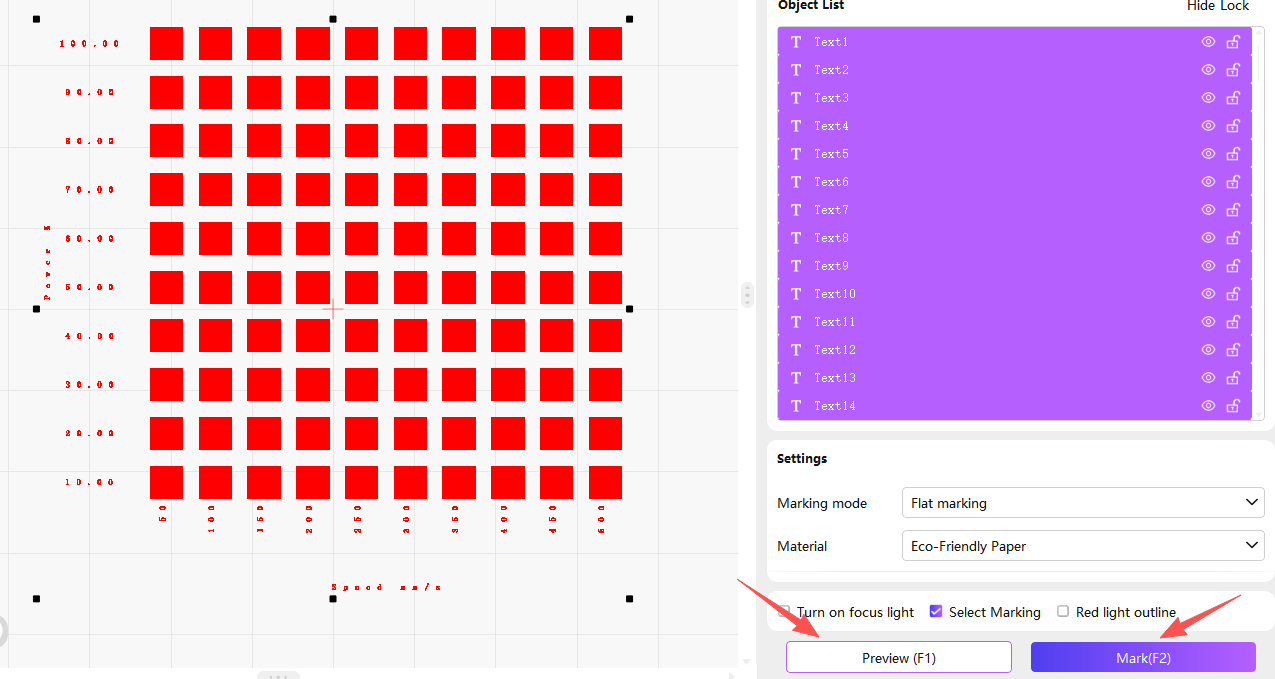
Select the test matrix, click Preview to verify marking position, then click Process to begin engraving.
7. Inspect Result & Save File
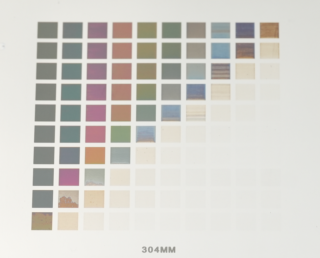
Inspect marking quality once processing finishes.
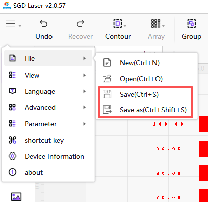
Critical Step: If you achieve satisfactory color results, save this test file without fail for reuse in formal color marking.
Note: After processing, apply protective oil such as WD40 on test samples. It enhances color visibility and prevents dark discoloration on marked surfaces.
8. Adjust Parameters for Further Testing
Modify one or multiple parameters including speed, power, frequency, focal length, line spacing and repeat testing until your target color is achieved.
Quick Reference: Where to Modify Each Parameter
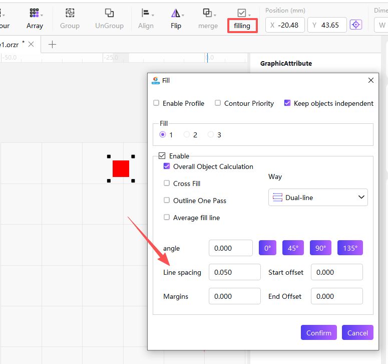
Parameter Type Modification Location Screenshot Variable Parameters Inside material matrix test panel Power / Speed / Frequency Parameter settings for the rectangle drawn in Step 1 Line Spacing Fill settings panel Focal Length (Defocus) Z-axis settings panel
Proceed to formal color marking once all testing is finished.
2. Formal Color Marking
1. Open Layer Separation Tool
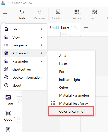
Click menu Advanced Settings → Color Mark to launch the layering tool.
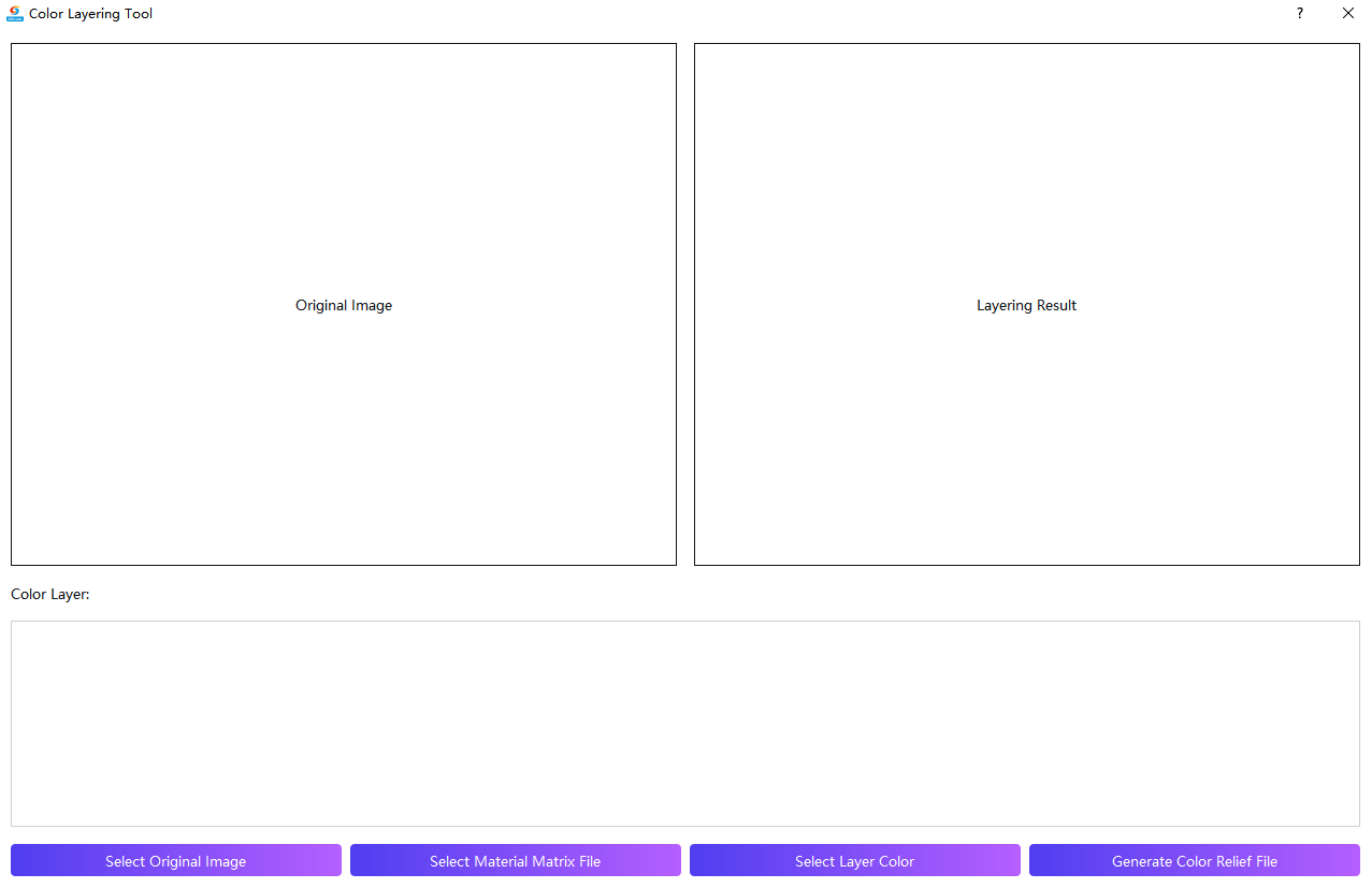 2. Import & Auto-Layer Graphic
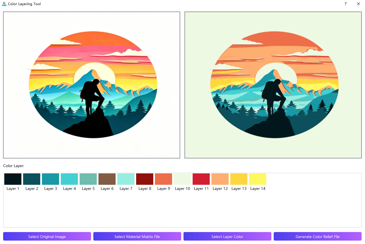
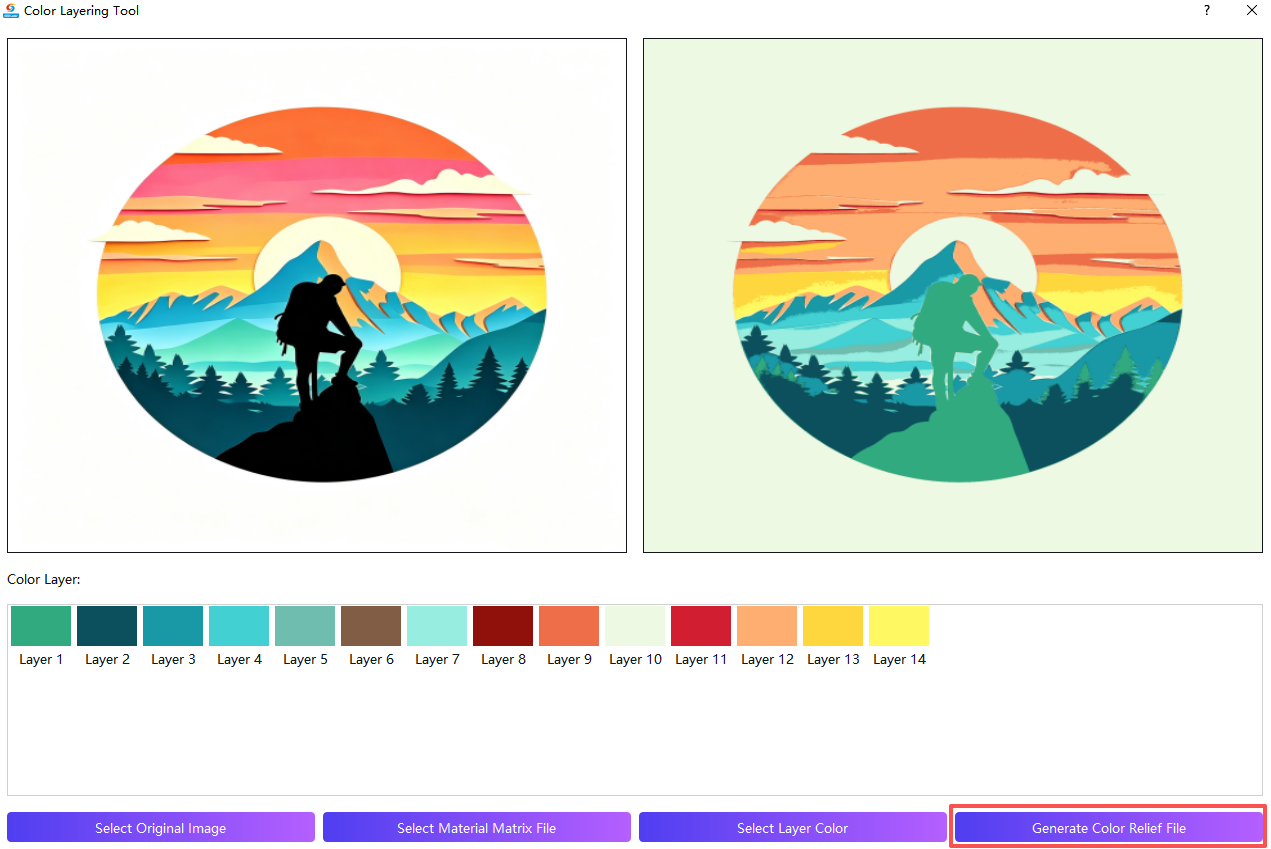
Click Select Original Image to import artwork; the software will automatically split the image into independent layers. The left pane displays original artwork; the right pane shows layered graphics ready for parameter assignment.
 3. Import Saved Material Matrix File
Click Select Material Matrix File and load the test file saved earlier.
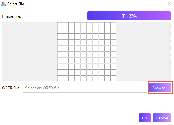
The Color Grid Editor will pop up after import. Each grid inside the editor matches the physical test grid parameters. Click any grid to edit reference colors and map them to actual marked samples one-to-one.
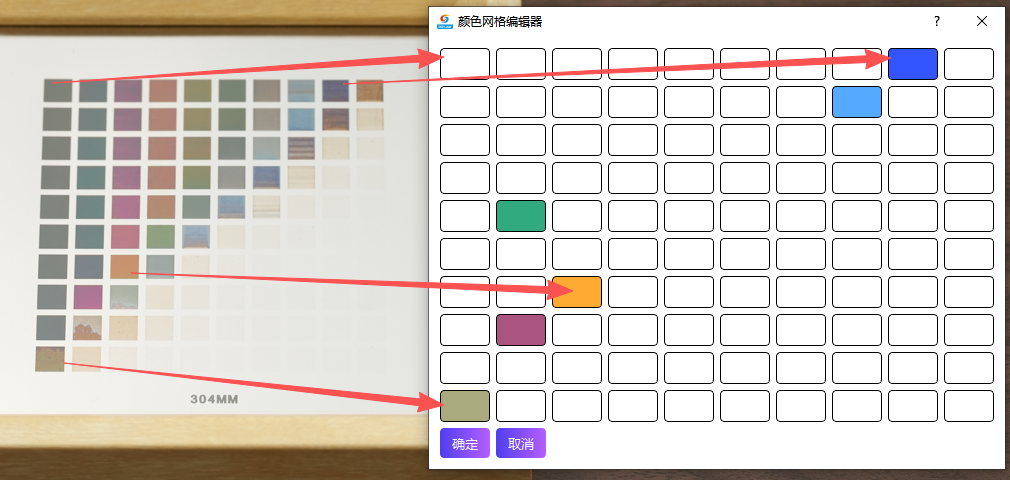
Tip: Color editing is optional; you may use physical test samples directly as color references.
Click Confirm after editing, then click Done to finish importing parameter file.
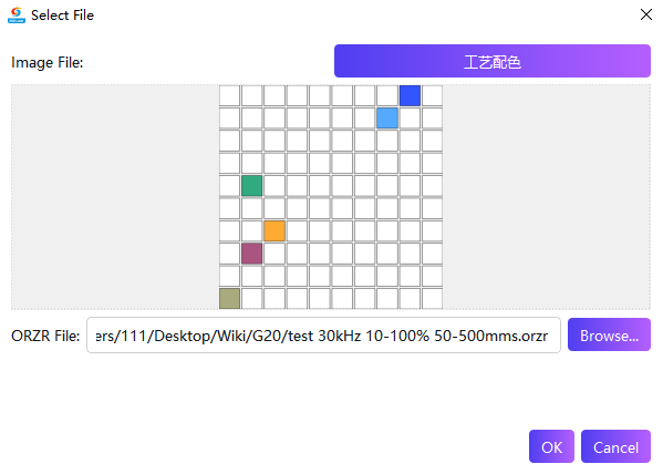
4. Assign Parameters to Each Layer
Select each layer to configure dedicated parameters. With layer selected, click Select Layer Color and pick the grid corresponding to your target color (green selected here for demonstration; match to your required color in real operation).
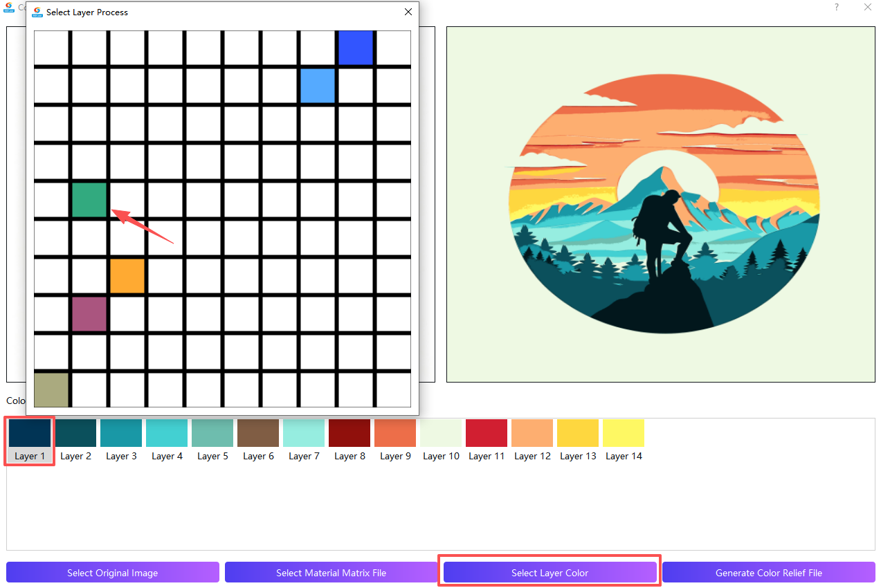 Close the pop-up window; the preview graphic on the right will display the color mapped from the selected grid.
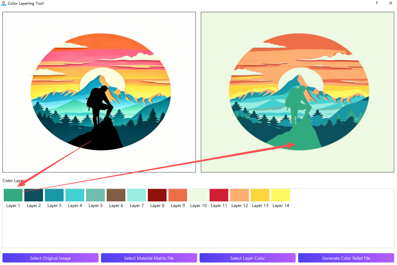 Repeat configuration for remaining layers until all layers are assigned matching parameter grids.
5. Generate Color Mark Job File
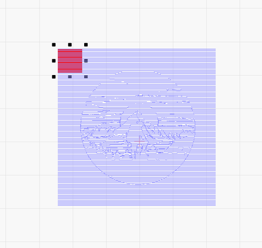
After all layer settings are complete, click Generate Color Mark File to export the processing file.
6. Place Workpiece
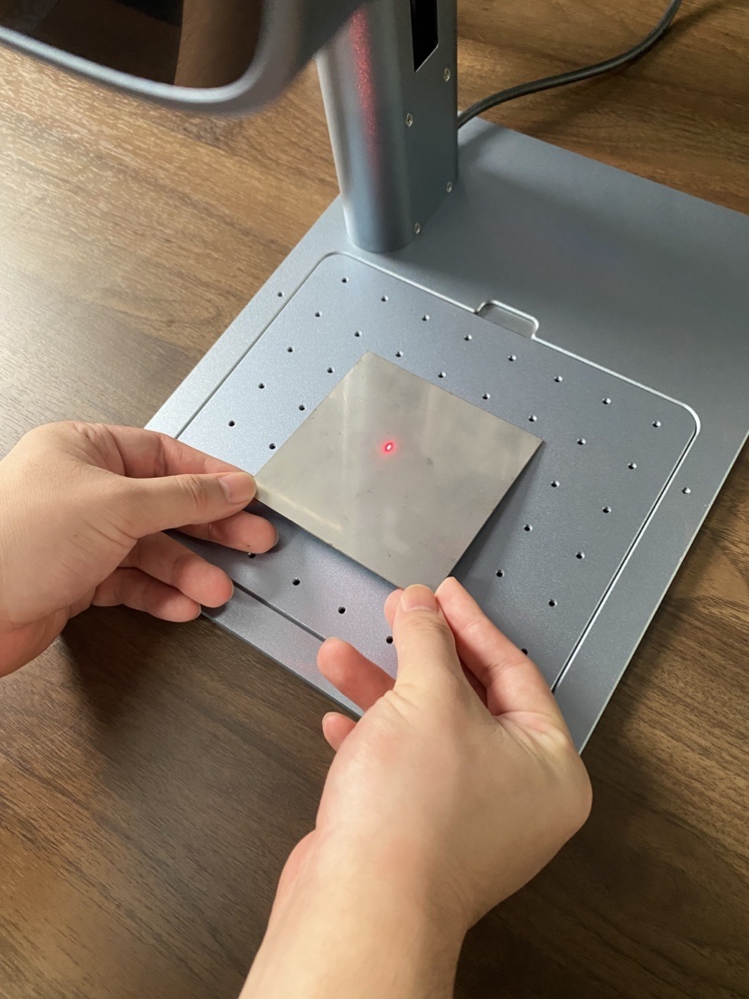
Adjust the distance between laser head and workpiece according to the focal length recorded in your test file.
7. Resize Graphic & Preview Marking Area
Resize and reposition your graphic, then click Preview to confirm marking coverage.
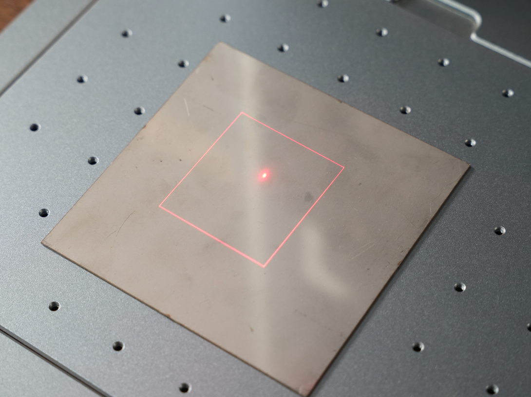
Note: Layer parameters inside this file perfectly match test matrix values and do not require modification; ensure the defocus offset matches your actual setup.
8. Start Color Marking
Click Mark to complete color engraving.