G20 Advanced Tutorial - Embossing Tutorial
Detailed Explanation of Relief Engraving Parameters
This article elaborates on all 3D relief parameters in SGD Laser. It is recommended to watch the tutorial video: Tutorial Video (Insert hyperlink here)
1. Enter Relief Interface & Import Assets
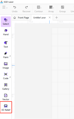
Open SGD Laser, create a new canvas, locate "3D Relief" on the left sidebar and click to enter the relief interface.
Go to the upper right corner and click "..." to import assets. Supported formats include stl, obj and some image formats.
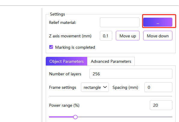
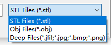
Images will be automatically converted to relief models after import. However, imported images may have incorrect aspect ratios, this function is still under optimization. It is recommended to prioritize importing 3D models (stl / obj) for relief engraving.
2. 3D Model Construction Parameters
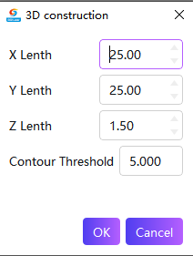
When importing image assets, the following basic dimension parameters need to be set to build the 3D model:
| Parameter | Description |
|---|---|
| X Length | Dimension of the model along the X-axis, directly determining the X-direction length of the relief. |
| Y Length | Dimension of the model along the Y-axis, directly determining the Y-direction length of the relief. |
| Z Length | Height of the model, corresponding to the engraving depth on the material. |
| Contour Threshold | Recognition threshold for edge blocks when converting images to models. Lower values deliver higher recognition precision but also introduce extra tiny unwanted blemishes. |
Incorrect X / Y / Z Length settings will cause distorted model proportions. Double-check dimensions before importing models.
3. Relief Engraving Processing Parameters
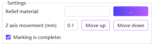
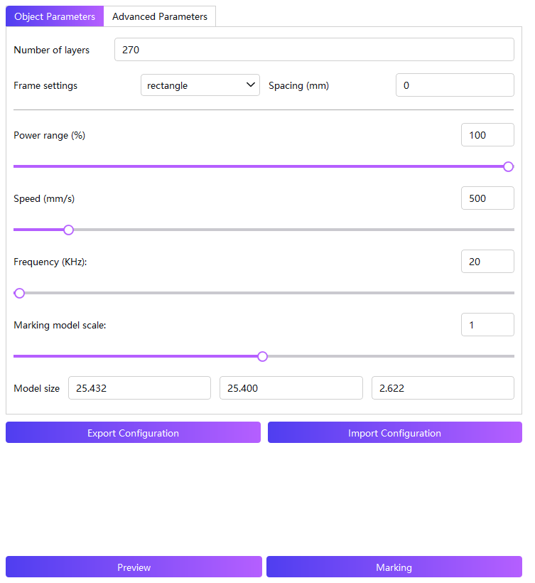
After importing assets, configure the following parameters in the processing panel: (Parameters for reference only)
| Parameter | Description |
|---|---|
| Relief Asset (...) | Import relief assets, supports stl, obj and partial image formats (images will auto-convert to relief models). |
| Move Z-axis | Z-axis travel distance controlled by software. |
| Restore Axis Position After Engraving | Choose whether the laser head returns to the starting position after engraving completes. |
| Layers | Default value: 30 layers. More layers deliver higher precision yet longer engraving time, adjust based on actual demands. |
| Outer Frame Settings | Set engraving shape, rectangular or circular, configure according to pattern and material requirements. |
| Margin | Offset distance between outer frame and model edges. Positive values expand the frame; negative values shrink it. |
| Power(%) | Percentage of laser output power. Higher values generate stronger energy and deeper marks; lower values produce weaker energy and shallower marks, adjust according to material properties and desired effects. |
| Speed(mm/s) | Travel speed of laser head. Faster speed boosts efficiency but may rough out details; slower speed enables fine engraving with lower efficiency, balance speed and marking quality. |
| Frequency(KHz) | Number of laser pulses emitted per unit time. High frequency creates dense pulses for smooth, delicate lines; low frequency delivers higher single-pulse energy to deepen marks, tune based on material and requirements. |
| Mark Model Scale | Adjust scaling ratio of the marked model; use preview to check marking coverage on the workpiece. |
| Preview | Preview engraving position; the red preview beam projects onto the material to display marking position and size. |
| Mark | Click to start the engraving job. |
4. Advanced Parameter Settings
| Parameter | Description |
|---|---|
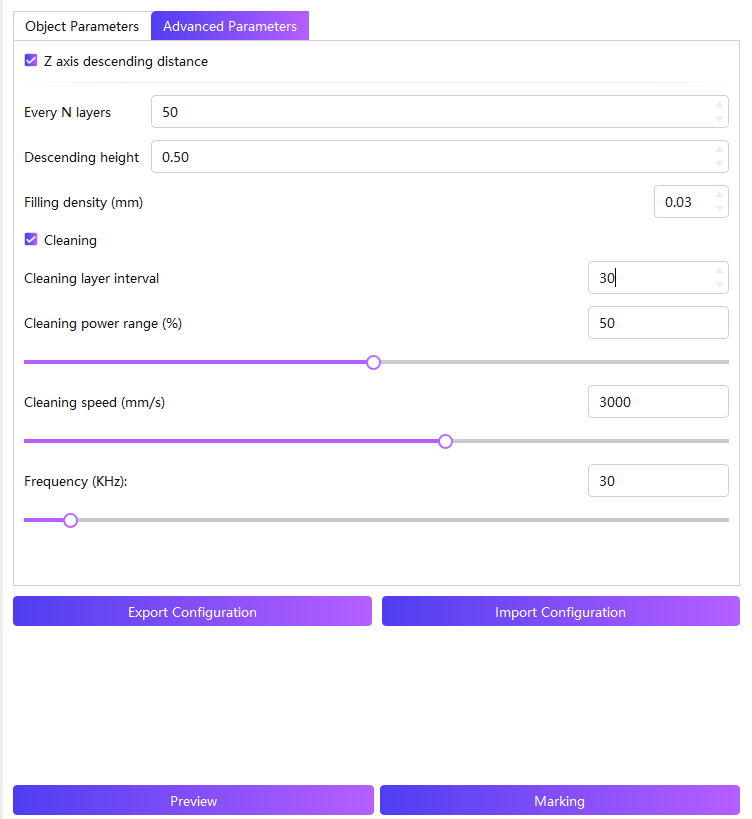
| Z-axis Descent Distance | When disabled, the laser head will not descend automatically and operates at a fixed height. When enabled, the laser head descends per set parameters to maintain the correct focal position. |
| Every N Layers | Execute one descent movement after finishing the specified number of layers. |
| Descent Height | Travel distance for each Z-axis descent movement. |
| Fill Density |
Line spacing for filling within each layer. Smaller values create denser fills with longer engraving time, balance processing time and marking quality. |
| Cleaning | Clean the workpiece to remove dust and surface blemishes; usually executed right after one layer completes before engraving the next layer. |
| Clean Layer Interval | Trigger one cleaning cycle after finishing the set number of layers. |
| Cleaning Power Range | Laser output power percentage for cleaning scans. Higher power enhances residue removal and surface cleaning, yet excessive power may scratch the workpiece surface, select appropriate power for your material. |
| Cleaning Speed | Travel speed of laser head during cleaning passes. Faster speed improves efficiency but loses fine details; slower speed delivers delicate cleaning with lower throughput, adjust as required. |
| Frequency | Number of laser pulses per unit time. High frequency produces dense pulses for smooth fine lines; low frequency carries higher energy per pulse for deeper etching. High frequency is generally used for delicate finishing touches. |