RA Pro/Pro Max Rotary Roller and Chuck - Accessories User Manual
RA Pro / Pro Max Rotary Roller & Chuck Kit User Guide
The RA Pro / Pro Max Rotary Roller & Chuck Kit supports SGD Laser (Galvo Only) and LightBurn software.
1. Software Configuration
1.1 SGD Laser
Launch SGD Laser software, connect the machine to your PC via USB and confirm successful connection. Open Device Information to view basic device info, modify accessory parameters and display settings.
Safety Tip: Close the safety door before marking with rotary roller or chuck.
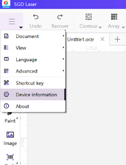
Device Information Interface
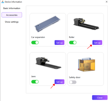
Admin Password: sculpfun001
Below are the built-in software parameters; you may adjust them according to your actual needs.
Rotary Roller
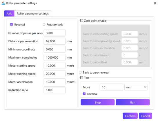
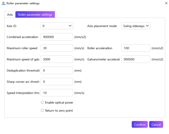
Built-in Roller Parameters
Chuck Jaws
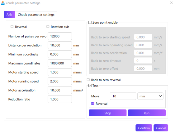
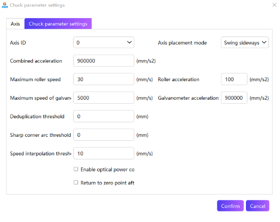
Built-in Chuck Parameters
1.2 LightBurn
Open the software and go to Tools - Rotary Setup. When using a galvo-based system with LightBurn software, the interface will appear different; please refer to the documentation provided with your specific galvo hardware components.
The following are the setup instructions for the frame-mounted unit.
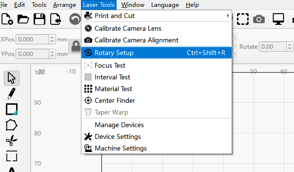
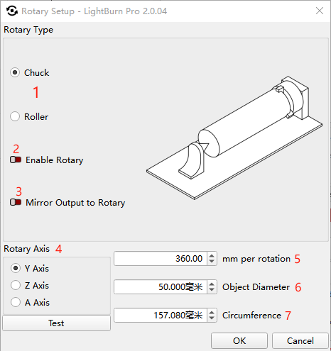
Descriptions for each rotary setup item are listed below:
| No. | Setting Item | Description |
|---|---|---|
| 1 | Toggle Roller / Chuck Mode | Switch between roller mode and chuck mode |
| 2 | Enable Rotary | Turn on rotary engraving function |
| 3 | Mirror Rotary Output | Enable mirrored output along the rotary axis |
| 4 | Rotary Axis | Select Y-axis to set the workpiece Y direction as rotation axis; Y-axis is the default |
| 5 | Rotary Speed | Set the recommended default value according to your machine model |
| 6 | Object Diameter | Diameter of the rotary workpiece; fixed at 20mm in roller mode; input actual workpiece diameter in chuck mode |
| 7 | Circumference | Circumference of the engraved workpiece; input value after manual measurement |
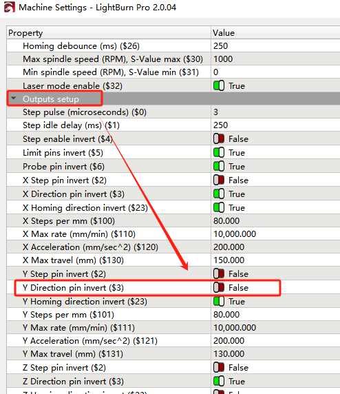
After enabling rotary function, adjust motor rotation direction via Tools - Machine Settings.
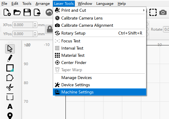
Locate Output Settings - Y Axis Direction Switch ($3), enable or disable this switch to reverse motor rotation as instructed in RA Pro Series Parameter Document.
2. Operation Steps (SGD Laser)
Demo Note: The following tutorial uses G9 Galvo Laser Module for demonstration.
2.1 Roller Engraving
Preparation
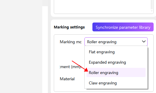
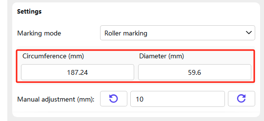
At the bottom-right corner of the SGD Laser canvas, switch engraving mode to Rotary Roller Marking.
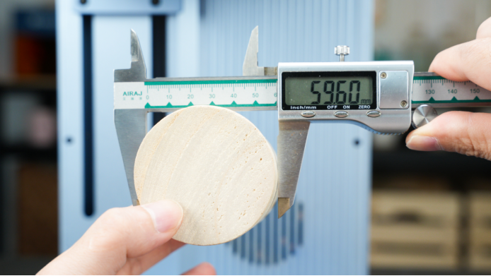
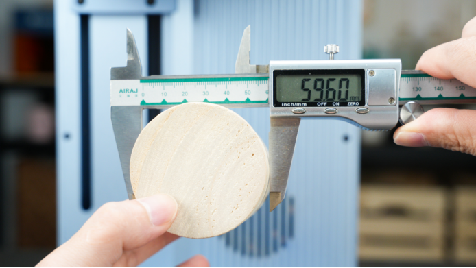
Measure workpiece diameter (or circumference) in advance and input the value into the corresponding software field.
Installation
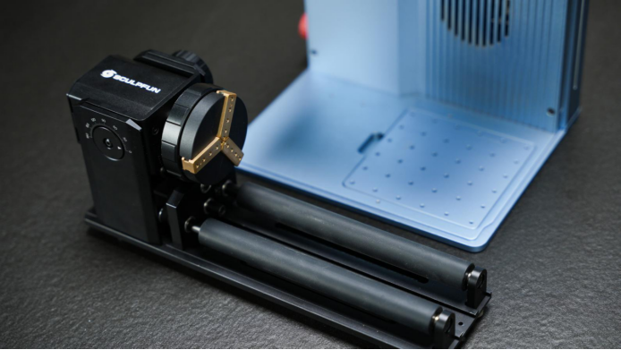
Remove the chuck assembly and mount the rotary roller onto the machine.
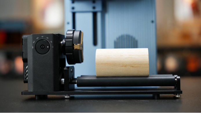
Place your workpiece on the rotary roller and slide the whole unit into the worktable.
Wiring Connection
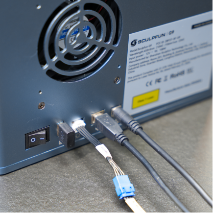
Connect one end of the RA2 cable to RA2 Pro, attach an adapter cable if needed, then plug the other end into the accessory port on the machine rear panel.
Engraving Operation
4.1 Focus Adjustment
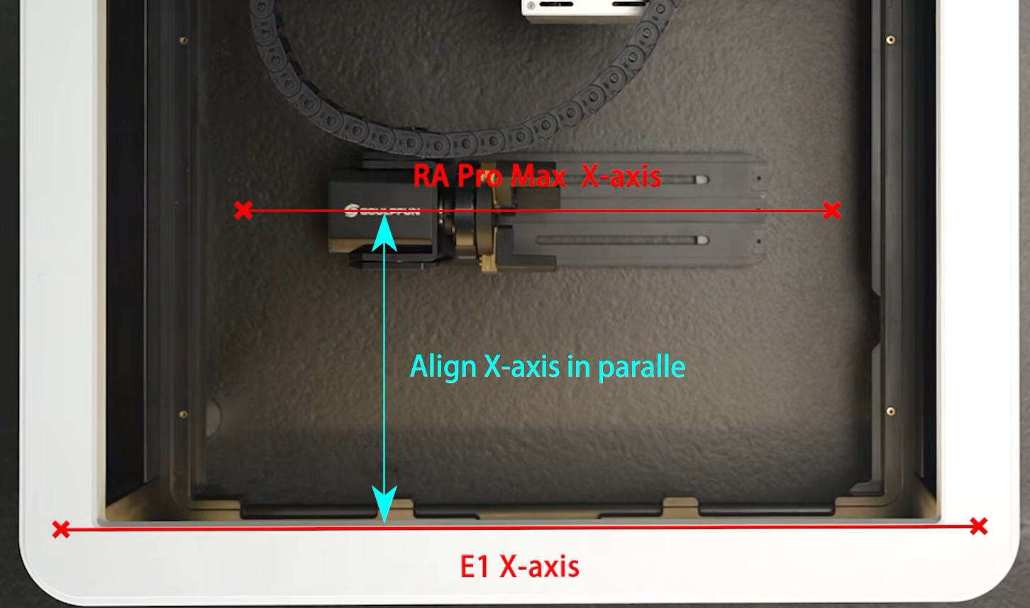
Note: Before focusing, reposition the roller to ensure the laser aiming dot lands on the highest point of your workpiece. Keep the roller perfectly horizontal to the machine for optimal engraving results.
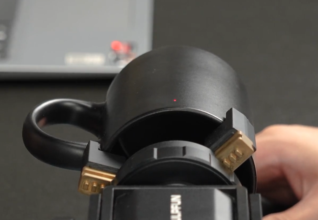
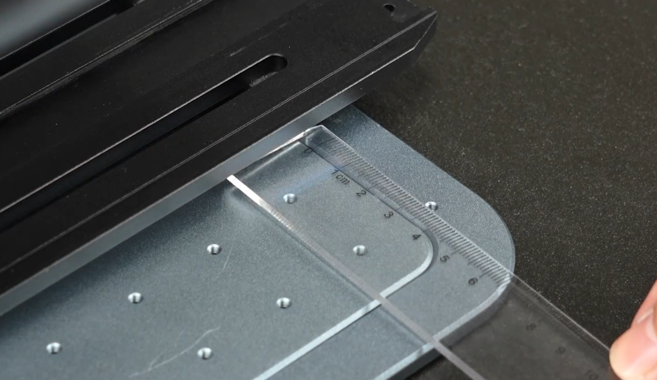
Place the loaded rotary assembly onto the machine, click Focus. A red dot and blue dot will project onto the workpiece surface; align the two dots to complete focusing.
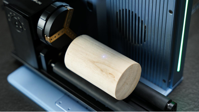
4.2 Parameter Setup
Edit patterns or text on the canvas and select suitable laser parameters based on your design and workpiece material; Special note: Rotary roller marking delivers poor performance for vector line engraving.
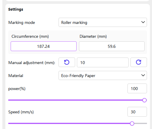
4.3 Frame Preview
Click Preview to view the full machine working boundary. The laser head will automatically return to origin after preview finishes.
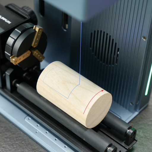
4.4 Start Marking
Click Mark to launch the engraving job.
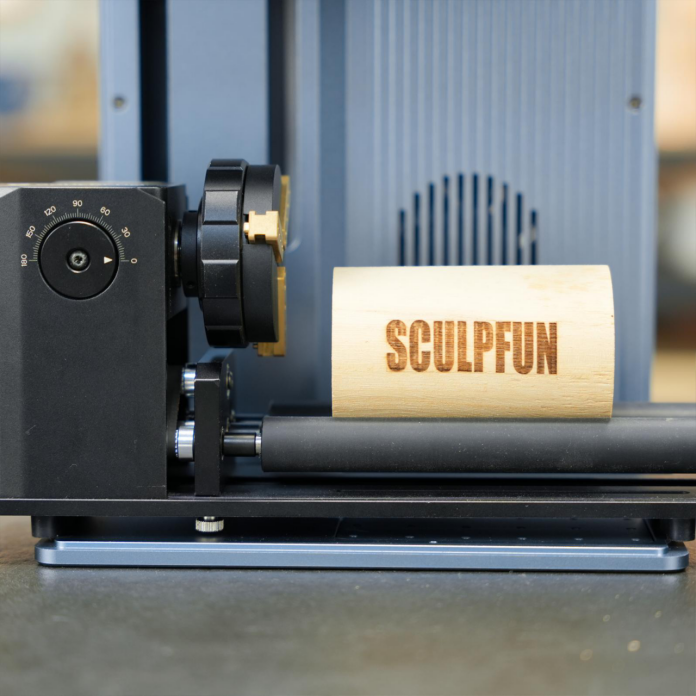
2.2 Chuck Engraving
Preparation
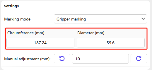
At the bottom-right corner of the SGD Laser canvas, switch engraving mode to Chuck Marking.
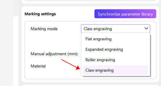
Measure workpiece diameter (or circumference) in advance and input the value into the corresponding software field.
Installation
Remove the rotary roller and mount the chuck assembly onto the machine.
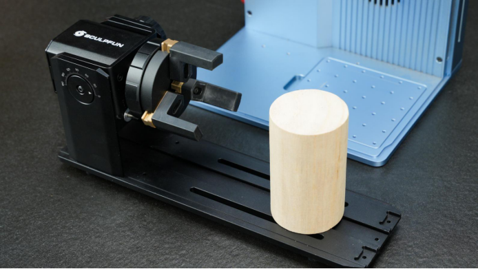
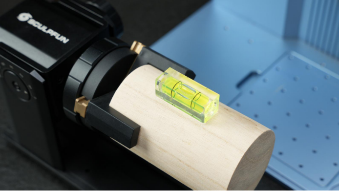
Secure your workpiece firmly inside the chuck to prevent slipping. Use a level to calibrate base horizontal alignment for precise pattern marking, then slide the entire chuck unit into the worktable.
Wiring Connection
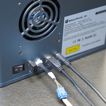
Connect one end of the RA2 cable to RA2 Pro, attach an adapter cable if needed, then plug the other end into the accessory port on the machine rear panel.
Engraving Operation
4.1 Focus Adjustment
Note: Before focusing, reposition the roller to ensure the laser aiming dot lands on the highest point of your workpiece. Keep the roller perfectly horizontal to the machine for optimal engraving results.
Place the loaded chuck assembly onto the machine, click Focus. A red dot and blue dot will project onto the workpiece surface; align the two dots to complete focusing.
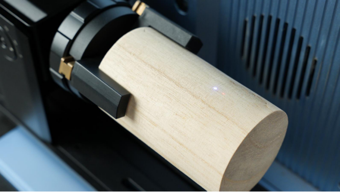
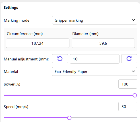
4.2 Parameter Setup
Edit patterns or text on the canvas and select suitable laser parameters based on your design and workpiece material.
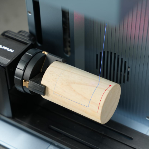
4.3 Frame Preview
Click Preview to view the full machine working boundary. The laser head will automatically return to origin after preview finishes.
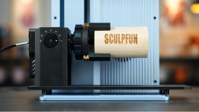
4.4 Start Marking
Click Mark to launch the engraving job.
3. Operation Steps (LightBurn)
Demo Note: The following tutorial uses E1 Laser Module for demonstration. Galvo machines require extra rotary motor parameter setup; refer to your dedicated machine manual for details.
3.1 Roller Engraving
Preparation
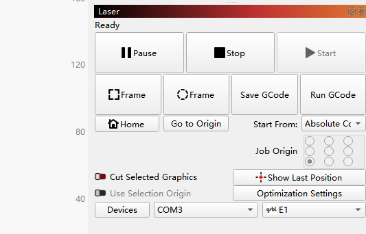
Launch LightBurn and establish machine connection.
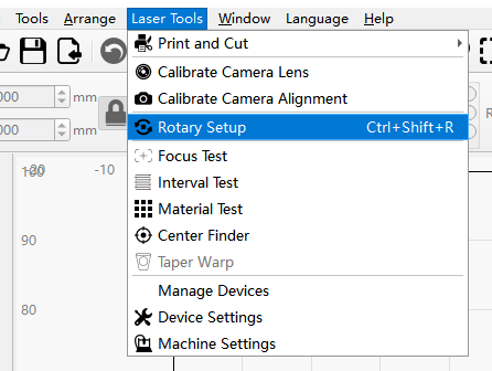
Navigate to Tools - Rotary Setup.
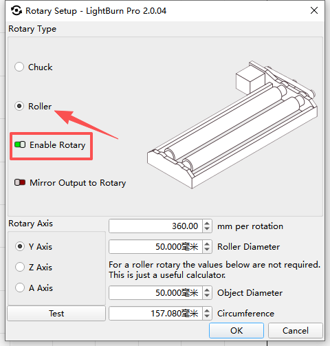
Select Roller Mode and toggle on Enable Rotary.
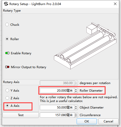
Configure parameters matched to your machine; full parameter list available in the Parameter Document. Gantry and galvo machines may need extra configuration; this demo uses E1 settings as example.
Installation
Slide the pre-assembled rotary roller kit into the machine worktable.
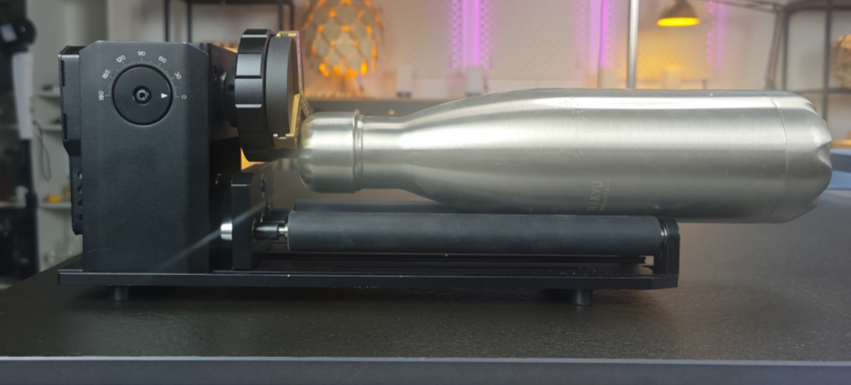
Place your workpiece onto the rotary roller.
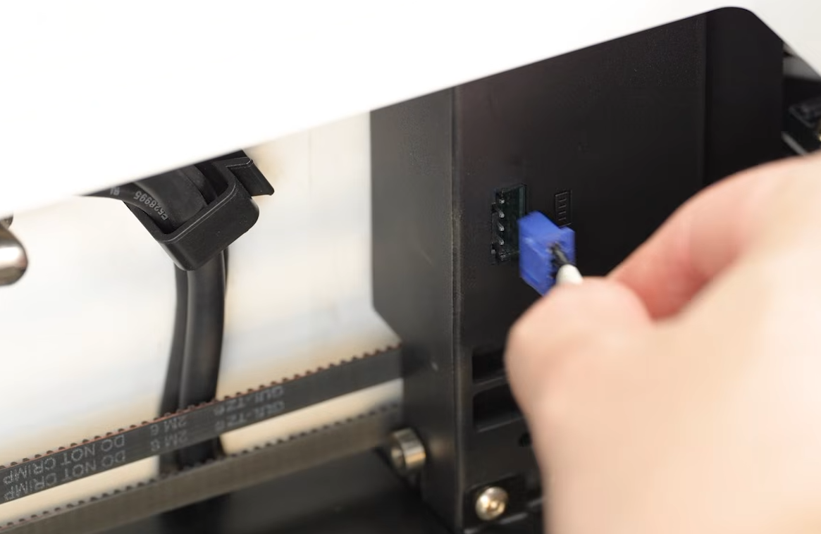
Wiring Connection
Connect the accessory to the machine with the supplied cable. Port assignments vary by machine model; check your machine manual for reference.
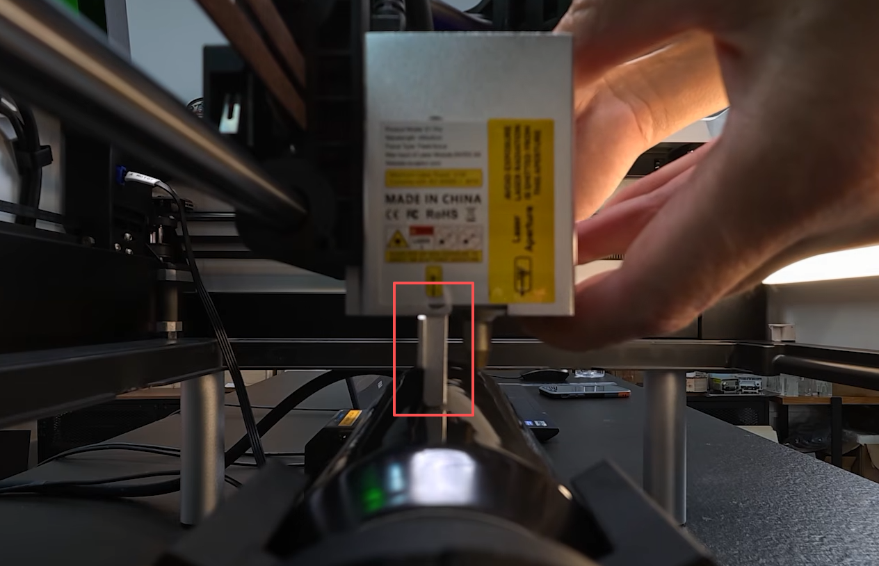
Engraving Operation
Complete focus adjustment, aim the laser focal point at the highest surface of the workpiece.
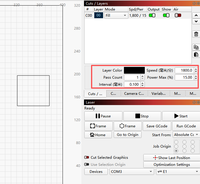
Draw or import your design file and set engraving parameters.
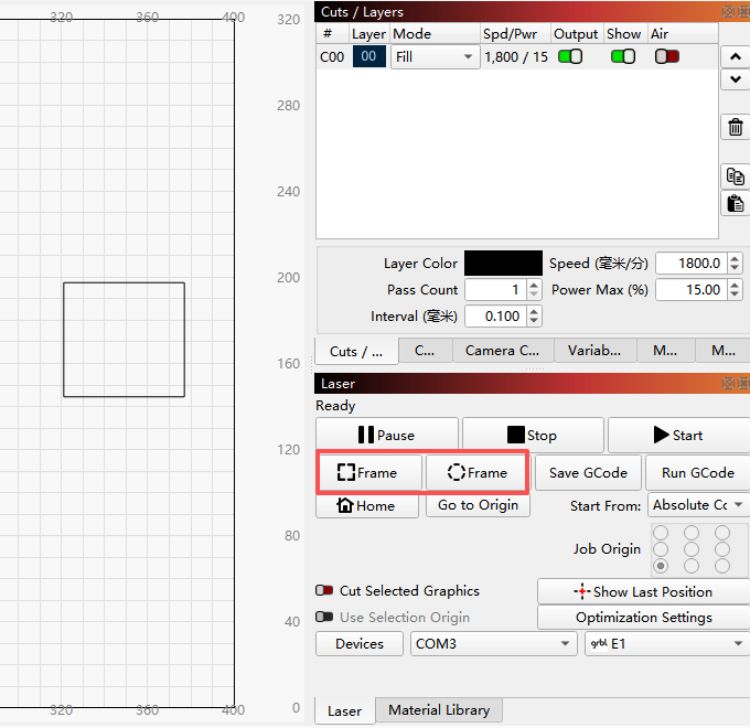
Use Frame preview to confirm engraving boundary position.
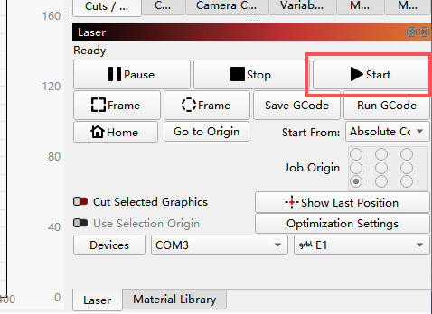
Click Start to begin processing.
3.2 Chuck Engraving
Preparation
Launch LightBurn and establish machine connection.
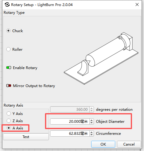
Navigate to Tools - Rotary Setup.
Select Chuck Mode and toggle on Enable Rotary.
Configure parameters matched to your machine and workpiece; full parameter list available in the Parameter Document. Certain machines may require extra machine setting adjustments; this demo uses E1 settings as example.
Installation
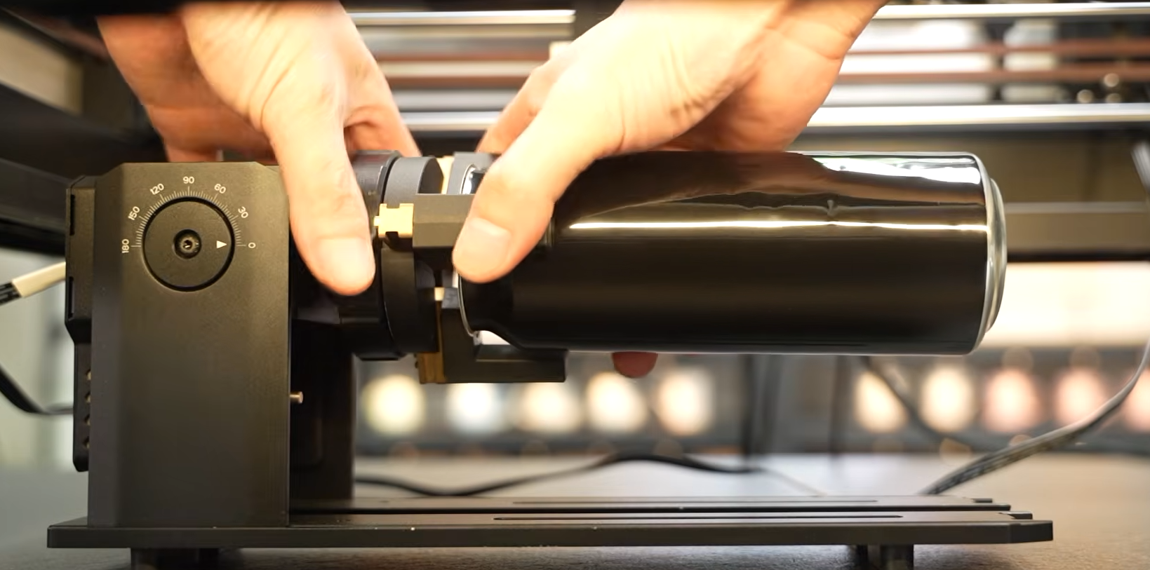
Slide the pre-assembled chuck kit into the machine worktable.
Secure your workpiece inside the chuck jaws.
Wiring Connection
Connect the accessory to the machine with the supplied cable. Port assignments vary by machine model; check your machine manual for reference.
Engraving Operation
Complete focus adjustment, aim the laser focal point at the highest surface of the workpiece.
Draw or import your design file and set engraving parameters.
Use Frame preview to confirm engraving boundary position.
Click Start to begin processing.