V5 Engraving Abnormality Correction Tutorial
During carving, if the pattern becomes deformed, it may be due to abnormal size ratio parameters. You can calibrate according to this document.
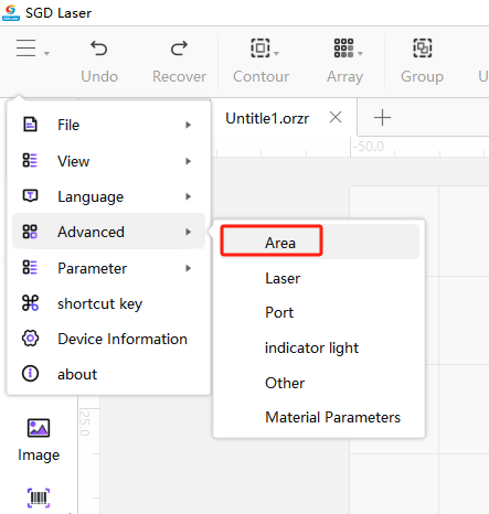
Open the software and connect the machine. Open the menu bar - Advanced - Area.
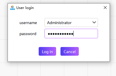
Enter administrator password: sculpfun001
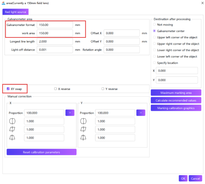
Enter the area settings.
Confirm that the galvanometer aperture and working area match the field lens. Here, a 150mm field lens is used as an example. Enable XY swap.
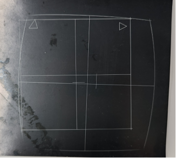
Place a dark, easily carvable material on the machine, covering the entire engraving area to prevent the laser from engraving onto the machine's base. You can also use the black coherence paper provided with V5. Then focus.
Click on the Marking calibration graphics, and the machine will perform the engraving.
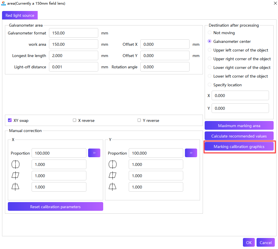
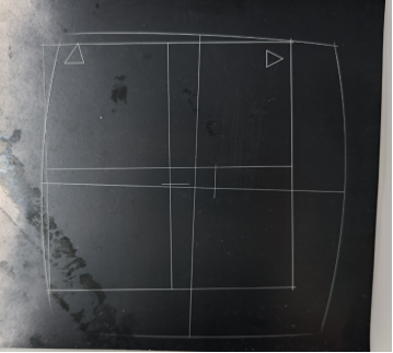
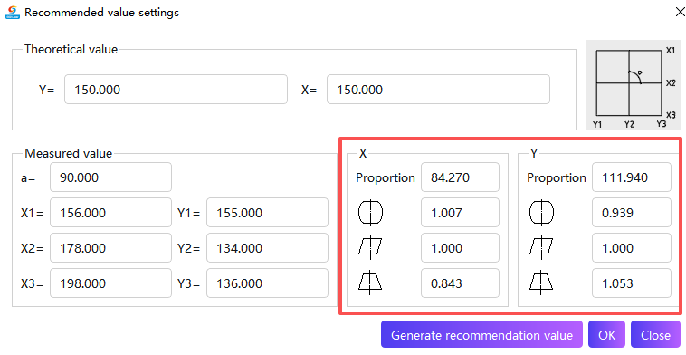
After the carving is completed, click Calculate recommended values, and the recommended value settings page will pop up.
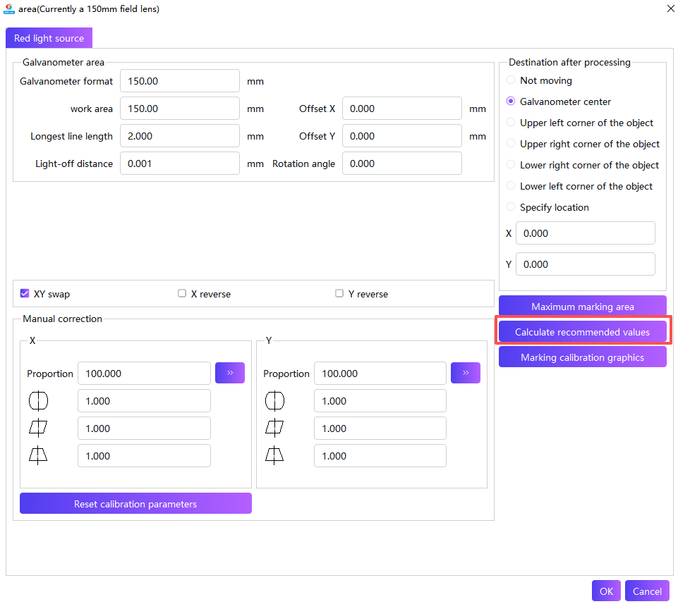
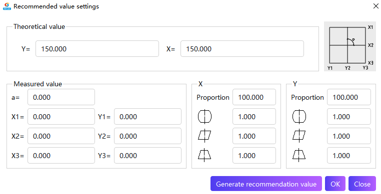
Theoretical value: Enter the selected field lens parameters (150mm\70mm).
Measured value: Measure the relevant values of the engraved pattern and input them.
a: The angle at the center of the square grid, as shown in the figure.
X1: Length of the first line in the horizontal direction.
X2: Length of the second line in the horizontal direction.
X3: Length of the third line in the horizontal direction.
Y1: Length of the first line in the vertical direction.
Y2: Length of the second line in the vertical direction.
Y3: Length of the third line in the vertical direction.
The figure on the right is a theoretical carving diagram.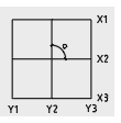
Based on the diagram, measure the relevant parameters and fill them in.
After completion, click Generate Recommendation Value, and the size ratio parameters will be generated on the right. Clicking Confirm will update them in the area settings.
Displace or replace the engraving material, then Marking calibration graphics again to observe the image. Multiple markings and calculations of recommended values can be carried out to obtain a set of engraving parameters close to the theoretical values, in order to achieve more precise calibration.
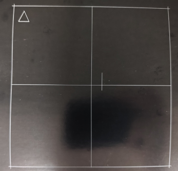
If you are not satisfied with the automatic parameter calculation, you can perform manual calibration.
Return to the area interface to perform manual calibration.
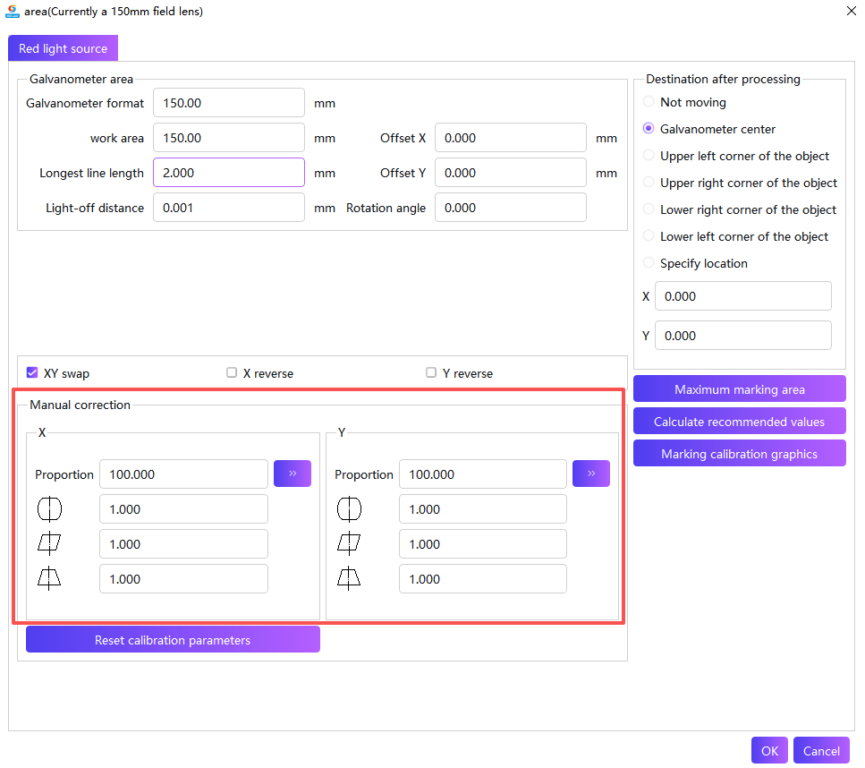
X: X-axis direction (horizontal parameter)
Y: Y-axis direction (vertical parameter)
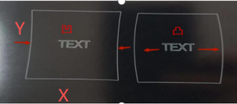
Curve adjustment : Adjust the curvature of the line. The larger the value, the more the line curves inward (0.8-1.2); the smaller the value, the more the line curves outward. Adjust the line until it is straight to complete the adjustment. You can use a ruler to measure the intersection points at both ends for observation.
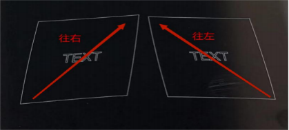
Parallel Tilt Adjustment : Adjust the parallelism of the lines. For the X-axis, the larger the value, the more the line tilts to the right (0.8-1.2); the smaller the value, the more the line tilts to the left. For the Y-axis, the larger the value, the more the line tilts to the upper right; the smaller the value, the more the line tilts to the upper left.
Adjust the lines to be horizontal or vertical to complete the adjustment. You can use a ruler to measure the intersection points at both ends, or you can determine the correction effect by observing the vertical and horizontal levels of X2/Y2.
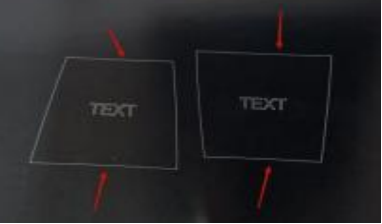
Trapezoid Adjustment : Adjust the gradient of the shape. The larger the value, the longer the top edge (X) or left side (Y), and the shorter the bottom edge (X) or right side (Y) (0.8-1.2); the smaller the value, the shorter the top edge (X) or left side (Y), and the longer the bottom edge (X) or right side (Y). Adjust the lines so that the top and bottom/left and right lengths are consistent to complete the adjustment.
Observe the calibration pattern, manually adjust the values, and mark again, repeating several times until the pattern approaches the theoretical pattern.
Then make proportional adjustments.
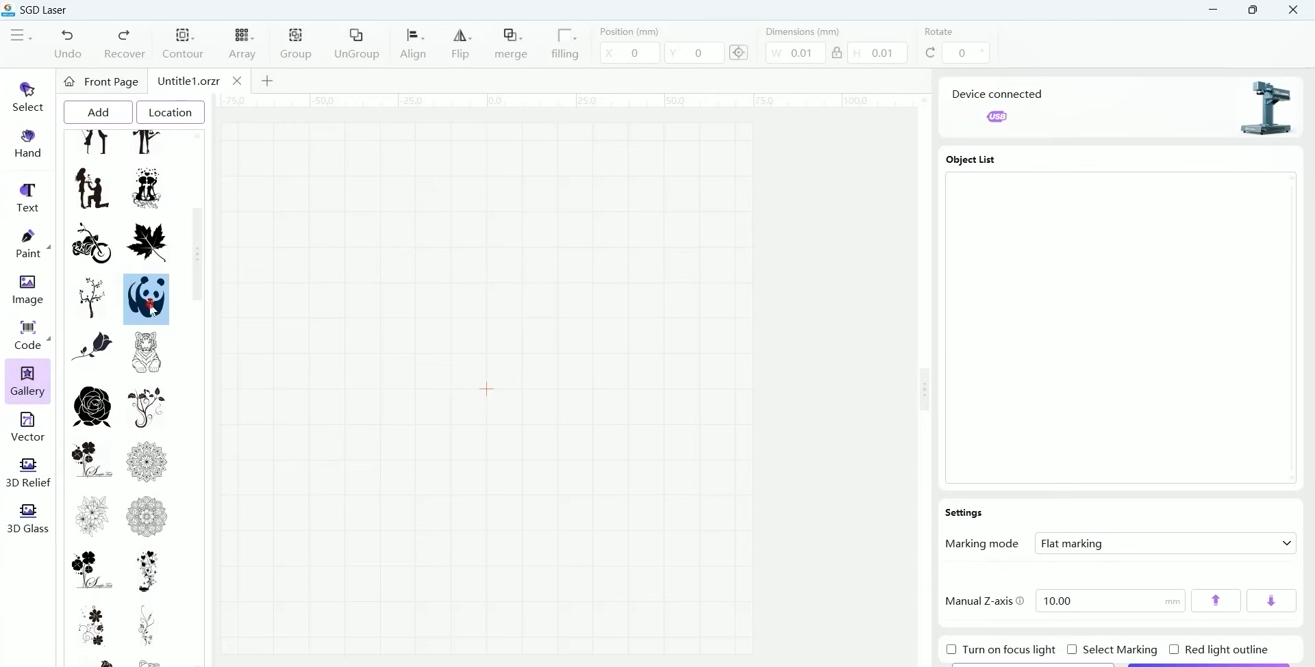
Exit the area settings and return to the canvas. Draw a 50*50mm rectangle.
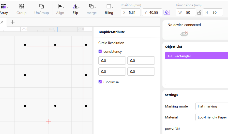
Click Preview to place the material in the right position, click Start to start marking.
Observe the graph, measure the length of the rectangular X/Y axis and record it.
Go back to the locale and tap Scale settings.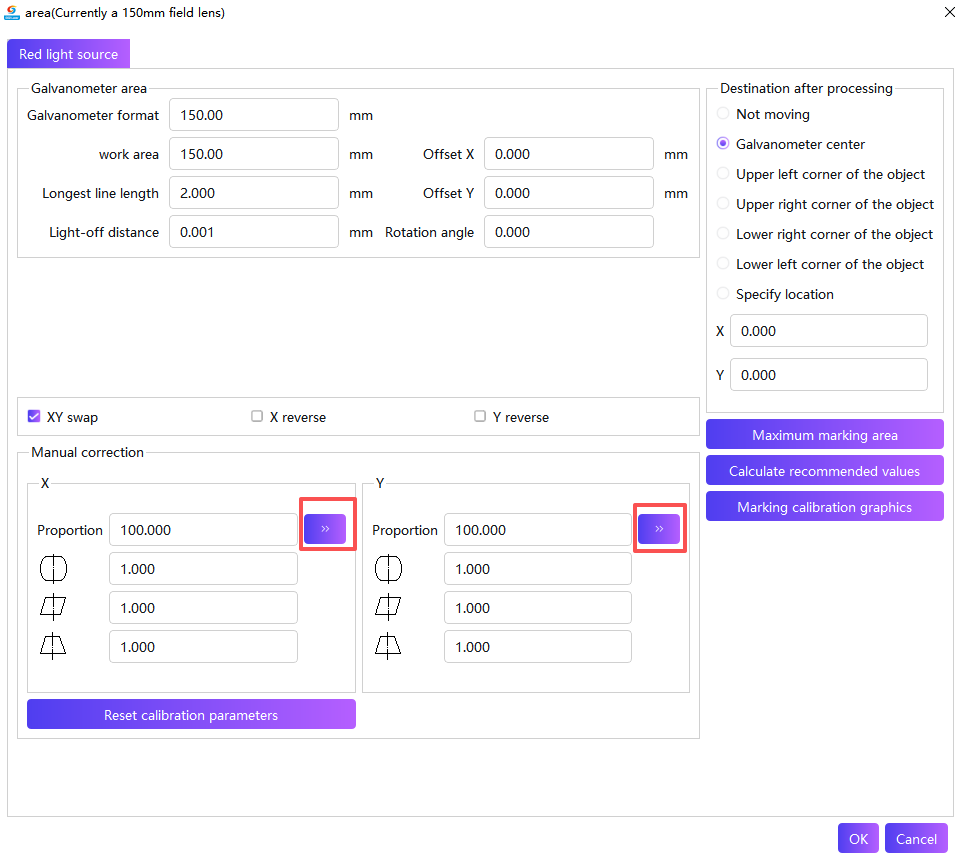
Fill in the target marking size and the actual marking size according to the measured values.
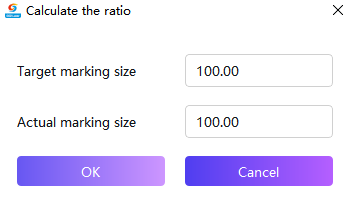
After clicking "OK," the scale will be automatically updated in the regional settings. You can perform several calibrations to achieve more accurate scale parameters. Calibration complete.